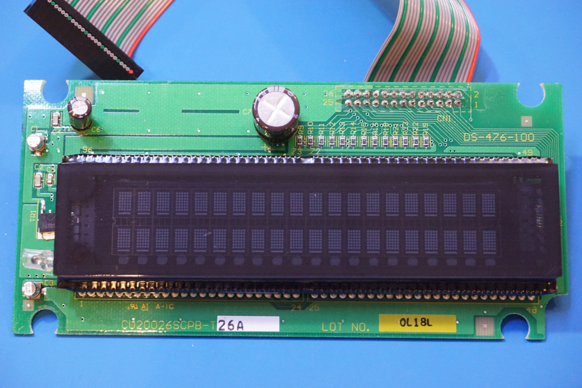
I recently bought a Noritake-itron VFD module off eBay. Noritake-itron specializes in making vacuum fluorescent displays for many OEMs. As such, there are many surplus modules being sold in secondary markets. The module I got has the model number CU20026SCPB-T26A, but unfortunately there’s not much information available on the internet for this specific model.
|
|
The good news is that most of the dot matrix Noritake VFDs use very similar protocols like this one (CU20026-TW200A), and the seller also provided some information regarding the pinout and the signaling information provided is largely in agreement with the datasheets for other Noritake VFDs.
Although most Noritake VFDs can be driven either in parallel or serial modes, the CU20026SCPB-T26A does not seem to have the jumpers found in other display modules to allow switching the drive mode. And according to the information from the seller, it appears that this particular board can only be driven in parallel mode.
Here is the pin out information for CU20026SCPB-T26A, the seller marked pins 10/12/14/16/18 as Vcc, but it appears that these pins are not being used and can safely be left afloat. If you have more information on this display, please post a comment below.
PIN Description                        PIN Description
 1   D7                                 2   Vcc (+5V)
 3   D6                                 4   Vcc (+5V)
 5   D5                                 6   Vcc (+5V)
 7   D4                                 8   Vcc (+5V)
 9   D3                                10   NC (Not used?)
11   D2                                12   NC (Not used?)
13   D1                                14   NC (Not used?)
15   D0                                16   NC (Not used?)
17   /WR (Write, active low)           18   NC (Not used?)
19   AD (Address/Data, data low)       20   Reset (active high)
21   /RD (Read, active low)            22   GND
23   /CS (Chip select, active low)     24   GND
25   Test (Low upon power up)          26   GND
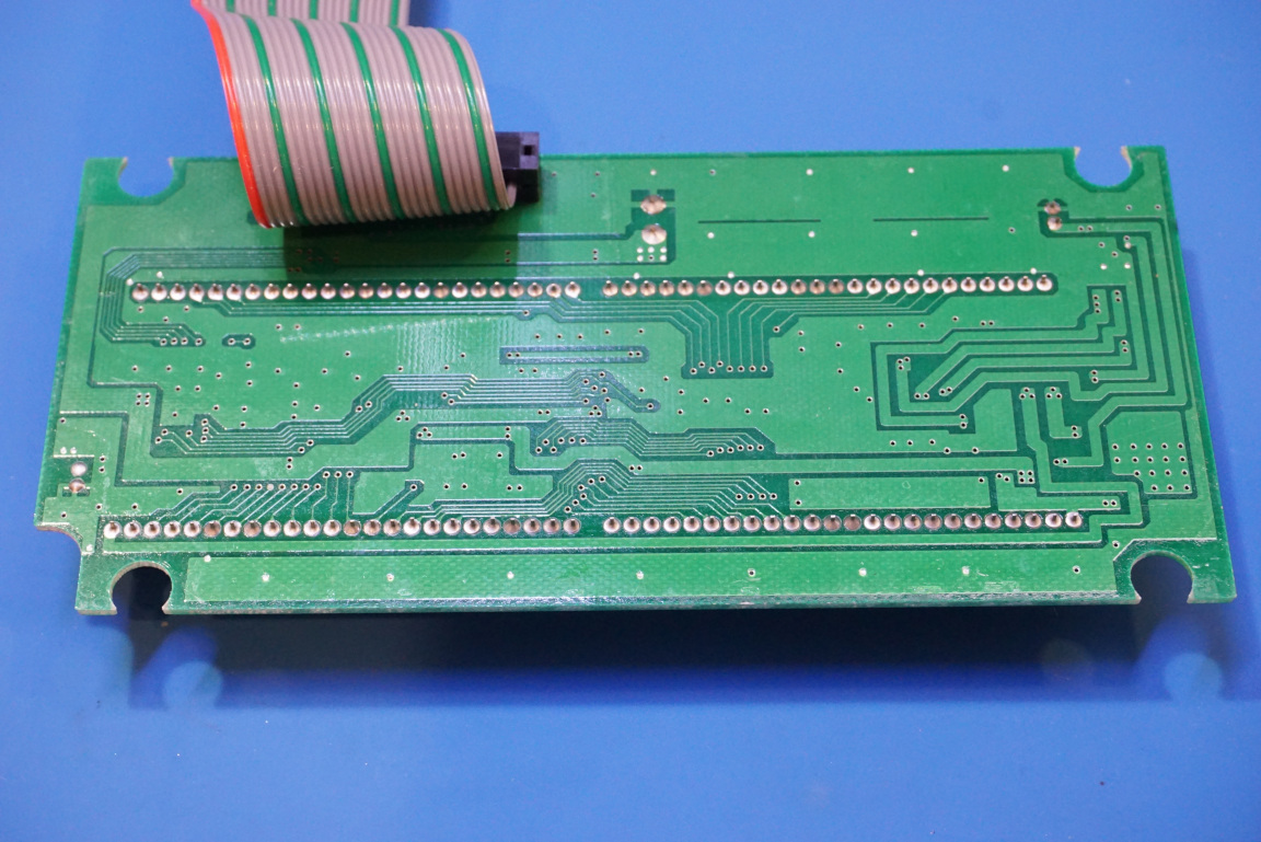
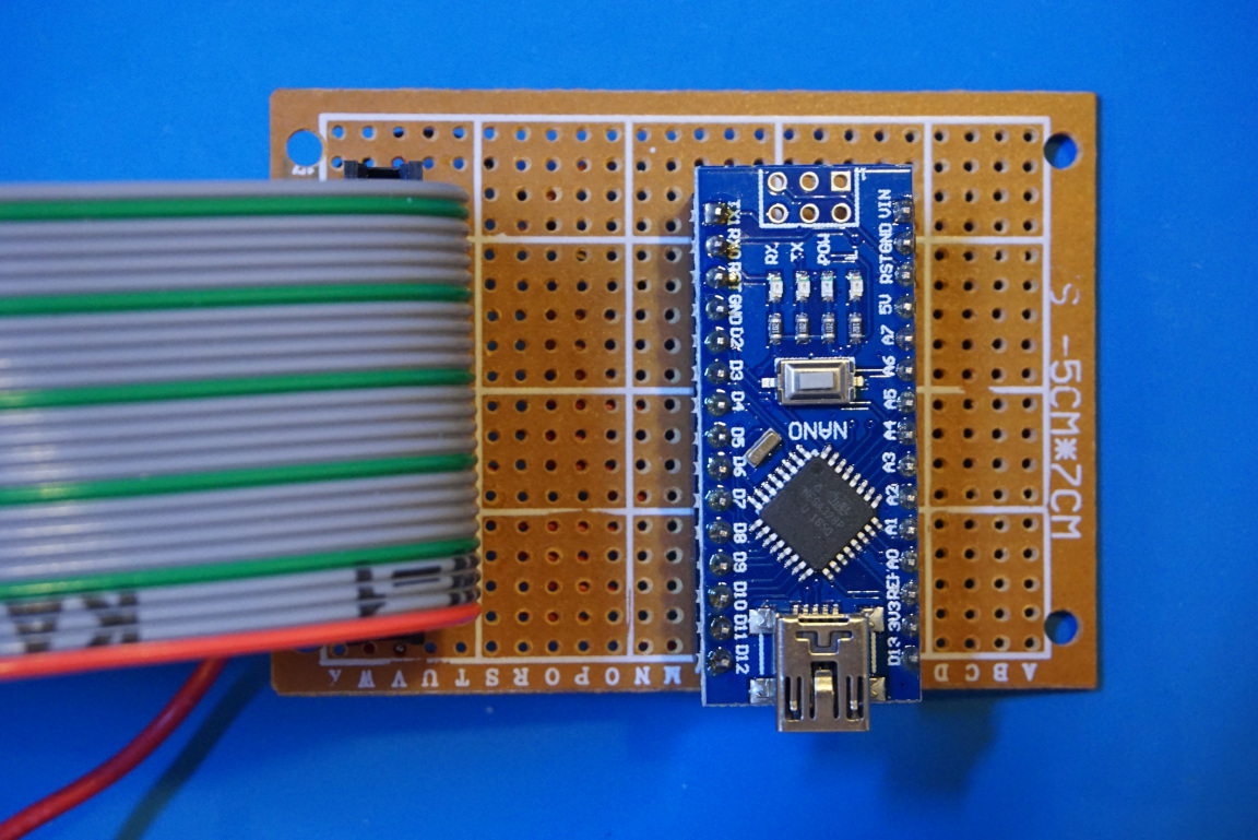
And here are a couple of pictures showing how the Ardunio nano is wired in regarding to the 26 pin dual row connector. For wiring convenience, the data pins D7-D0 are connected with Arduino’s digital pins 12 through 5. The four control pins (/WR, AD, /RD, /CS) are connected to Arduino’s digital pin 4, 3, 2 and 13.
According to the datasheet, the RD pin can be used to query whether the VFD has finished processing the issued command. Since different command takes different amount of time to finish, using the RD pin can achieve the tightest timing. For simplicity though, we could just insert some delays after each command, as long as the delay is longer than the longest time for command completion we should be fine. In practice, 1 ms is more than adequate. Adding in this fixed delay time lowers the throughput, but in practice this slight degradation in performance is not noticeable. So although the RD pin is used, it is merely tied to high (so it’s for data mode rather than reading mode). You could just tie it to Vcc and free up a pin if desired.
|

|
And here is the Arduino code for testing the functionality of the VFD. The most crucial function is the setData(byte b) function. This function takes in an ASCII character that is to be sent to the display and sets each bit (D7-D0) on the data bus accordingly.
To display a character, call the writeData(byte b) function, which sets up the AD, WR and CS line and calls setData. Data is written to the VFD when the WR pin is transitioned from low to high. The built-in hardware of the Noritake VFD automatically advances the cursor by one so writing consecutive characters is as simple as calling the setData function many times with different data.
The moveCursorTo(int i) function moves the cursor to the location indicated by the input parameter. The possible range is 0-39 for this display, with 0-19 representing the positions on the first row and 20-39 for the positions on the second row.
Finally, there are a few commands that is supported by CU200026SCPB-T26A. You can turn the cursor on and off (CUSOR_ON, CUSOR_OFF) and change the display mode between normal (DSP_NORMAL) and horizontal scroll (DSP_HSCROLL). The horizontal scroll mode is particularly useful, it shifts the content in the second row to the first row and clears the second row when the second row is full, giving you the scroll effect.
The sample code here does nothing more than echoing whatever is being sent through the serial port (e.g. with Arduino’s built-in serial terminal), but it is very useful for testing the capabilities of the display.
const int D7 = 12;
const int D6 = 11;
const int D5 = 10;
const int D4 = 9;
const int D3 = 8;
const int D2 = 7;
const int D1 = 6;
const int D0 = 5;

const byte D[]={D0, D1, D2, D3, D4, D5, D6, D7};

const int WR = 4;
const int AD = 3;
const int RD = 2;
const int CS = 13;

const int DSP_NORMAL = 0x11;
const int DSP_HSCROLL = 0x12;
const int CURSOR_ON = 0x13;
const int CURSOR_OFF = 0x14;

void initPins()
{
  for (int i = 0; i < 8; i++)
    pinMode(D[i], OUTPUT);

  pinMode(WR, OUTPUT);
  pinMode(AD, OUTPUT);
  pinMode(RD, OUTPUT);
  digitalWrite(RD, HIGH);
  pinMode(CS, OUTPUT);
  digitalWrite(CS, HIGH);
}

void setData(byte b) {
  for (int i = 0; i < 8; i++) {
    digitalWrite(D[i], ((1 << i) & b) >> i);
  }
}

void writeData(byte b) {
  digitalWrite(AD, LOW);
  digitalWrite(WR, HIGH);
  digitalWrite(CS, LOW);
  setData(b);
  digitalWrite(WR, LOW);
  delay(1);
  digitalWrite(WR, HIGH);
  digitalWrite(CS, HIGH);
  delay(1);
}

void resetScreen() {
  digitalWrite(AD, HIGH);
  digitalWrite(WR, HIGH);
  digitalWrite(CS, LOW);
  setData(0x40);
  digitalWrite(WR, LOW);
  delay(1);
  digitalWrite(WR, HIGH);
  digitalWrite(CS, HIGH);
  delay(1);
}

void moveCursorTo(int i)
{
  digitalWrite(AD, HIGH);
  digitalWrite(WR, HIGH);
  digitalWrite(CS, LOW);
  setData(i);
  digitalWrite(WR, LOW);
  delay(1);
  digitalWrite(WR, HIGH);
  digitalWrite(CS, HIGH);
  delay(1);
}

void setup() {
  initPins();
  Serial.begin(9600);
  resetScreen();

  writeData(DSP_HSCROLL);
  writeData(CURSOR_OFF);
}

void loop() {
  if (Serial.available() > 0) {
    writeData(Serial.read());
  }

}
Here is a short video demonstrating how to use this VFD.

