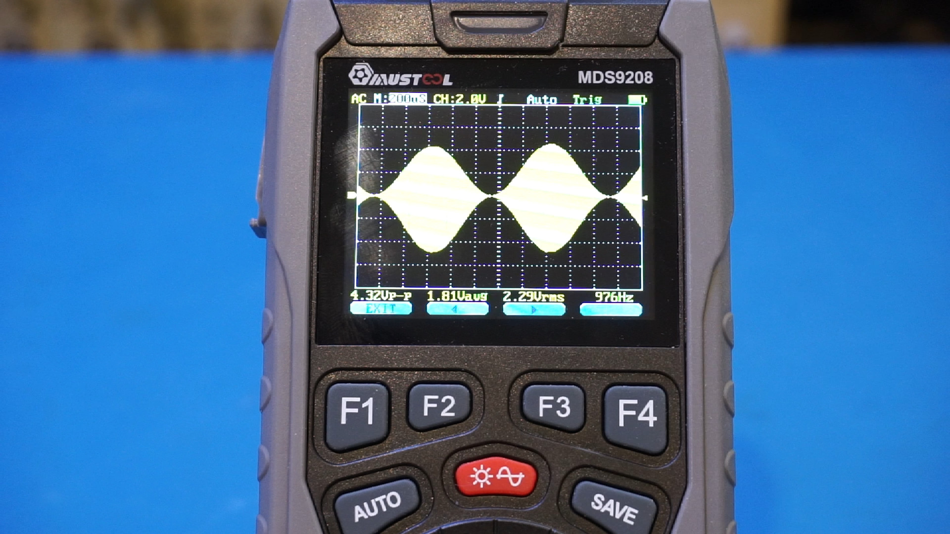
I did a detailed review of a MUSTOOL MDS9208 3-in-1 digital multimeter, oscilloscope (12 MHz) and signal generator (see video link below) and in this blog post I will share some of the teardown pictures.
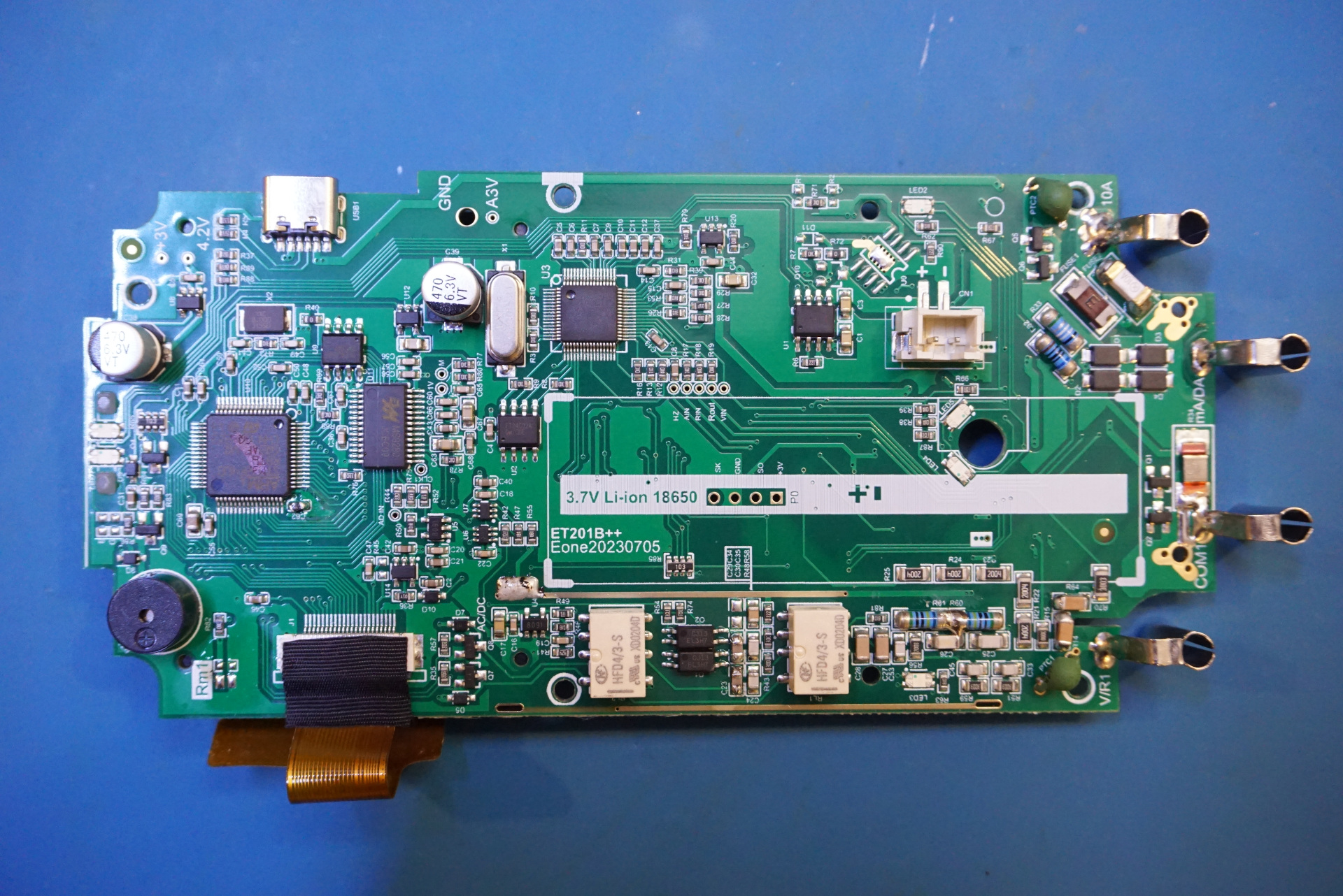
Here are a couple of pictures showing the main board. In the picture to the right below, the shielding of the oscilloscope input section has been removed.
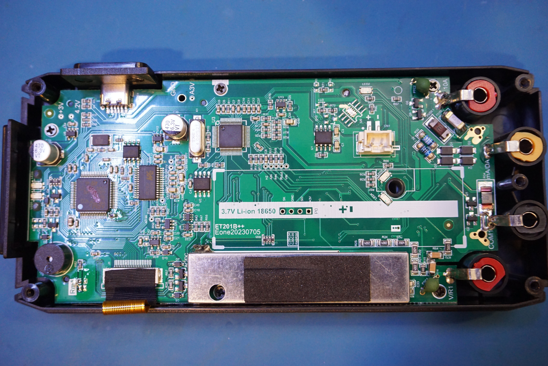
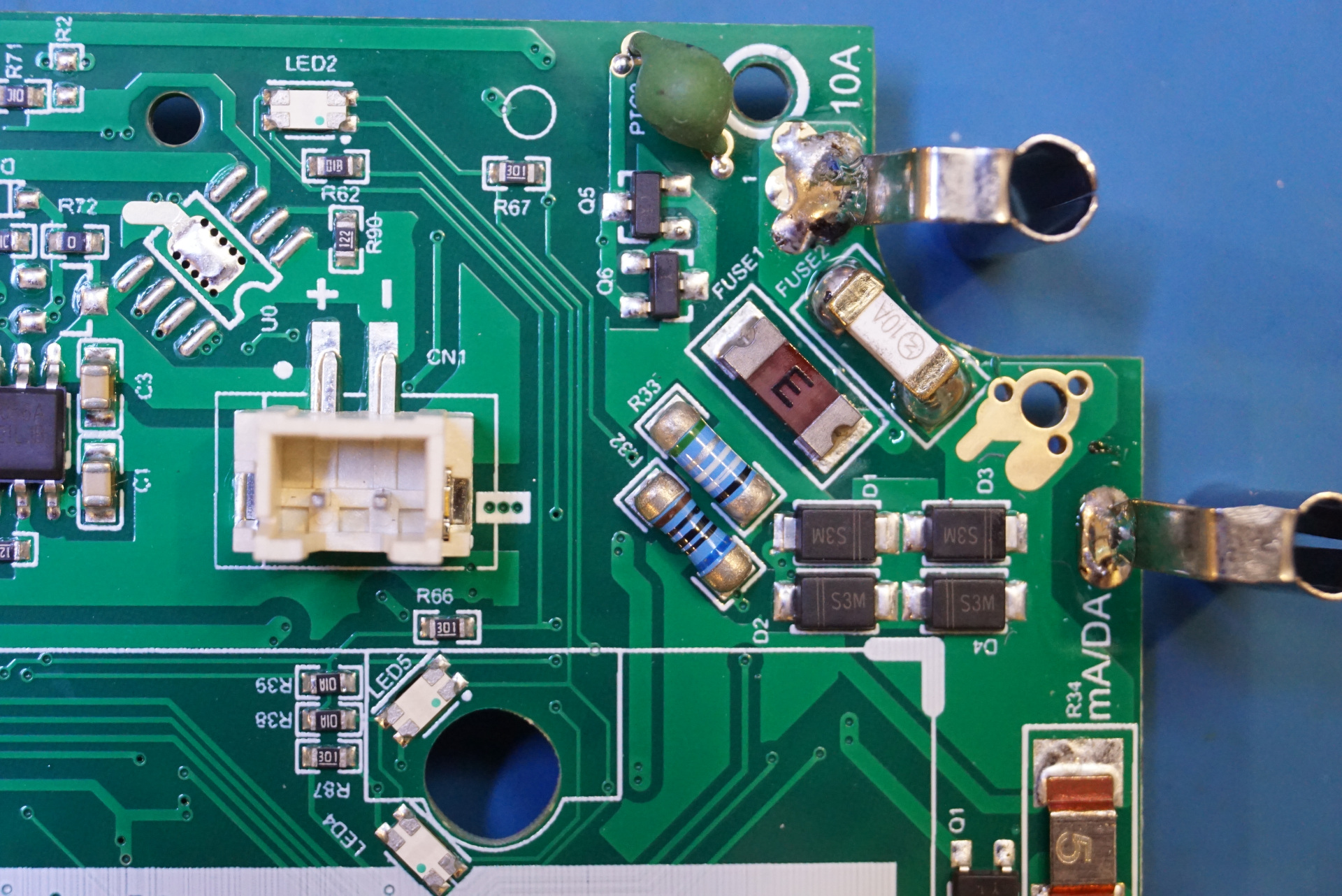
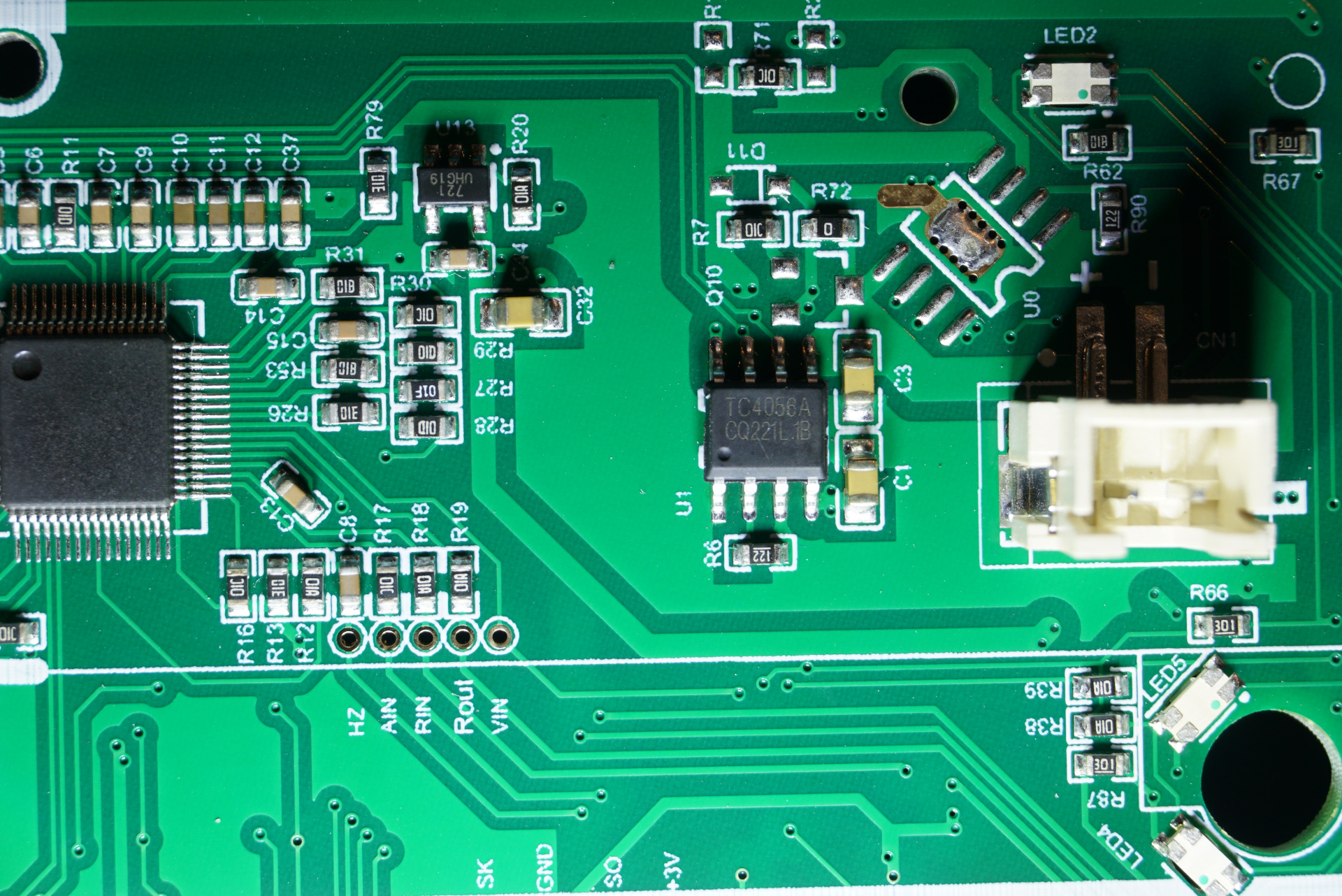
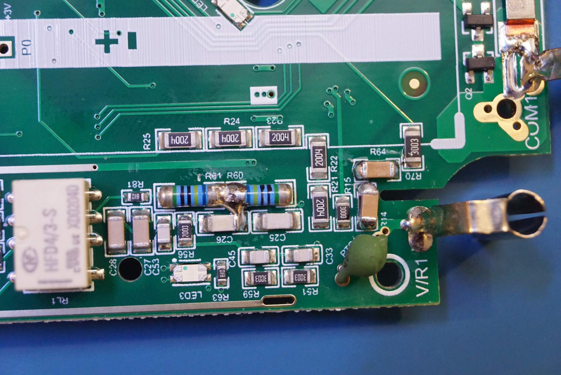
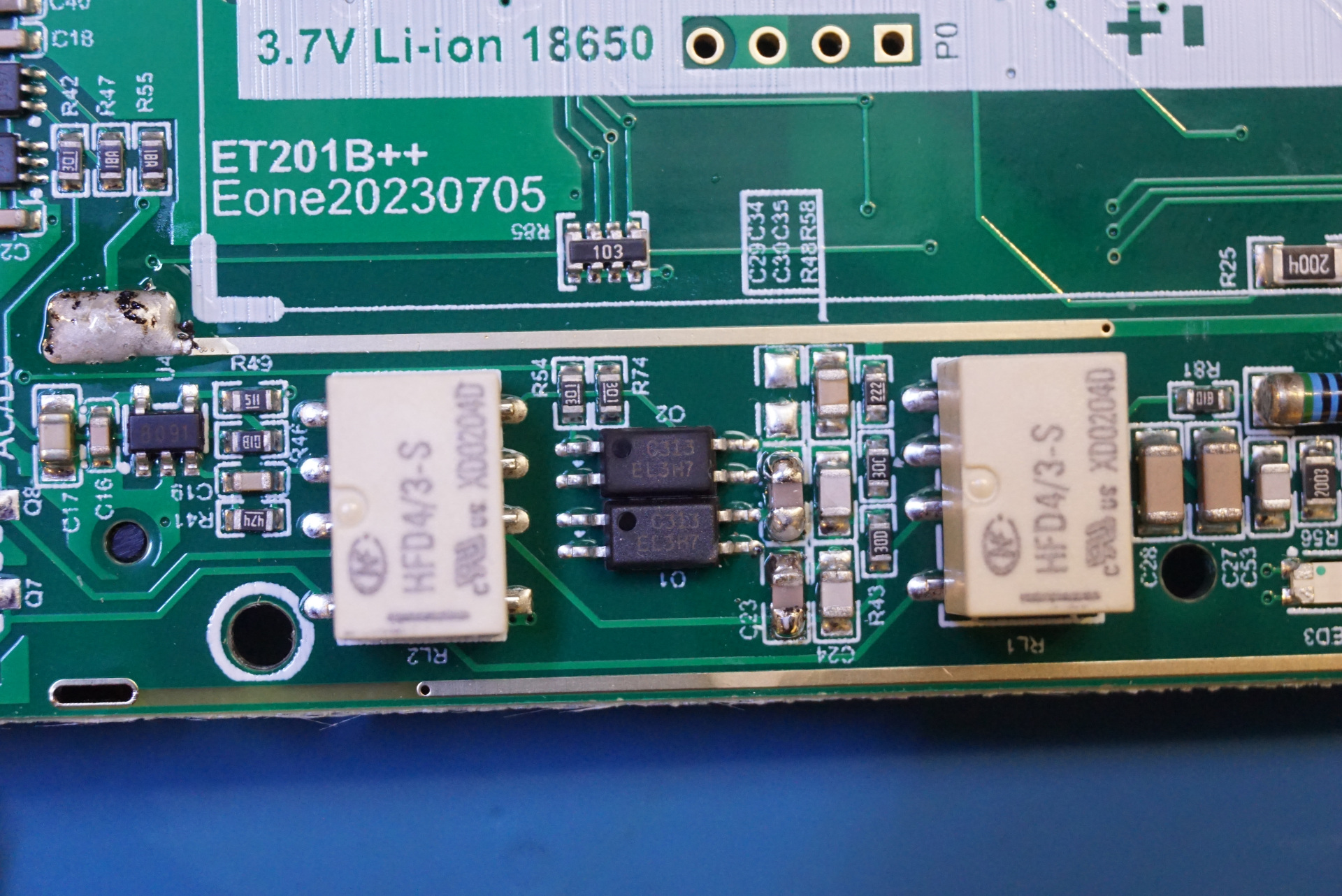
The picture to the left below shows the current range section. You can see the fuses for both the lower current and high current ranges. The current shunt for the amp range is also visible. In the picture to the right you can see the connector for the battery and the TC4056A battery charger chip.
Here is a close up of the multimeter section. The multimeter chip is unmarked.
Here are a couple of pictures showing the input section of the oscilloscope. You can see five 2 MΩ resistors in series giving the 10 MΩ input impedance. Putting these resistors in series instead of using just a single 10 MΩ resistor also increases the withstand voltage.
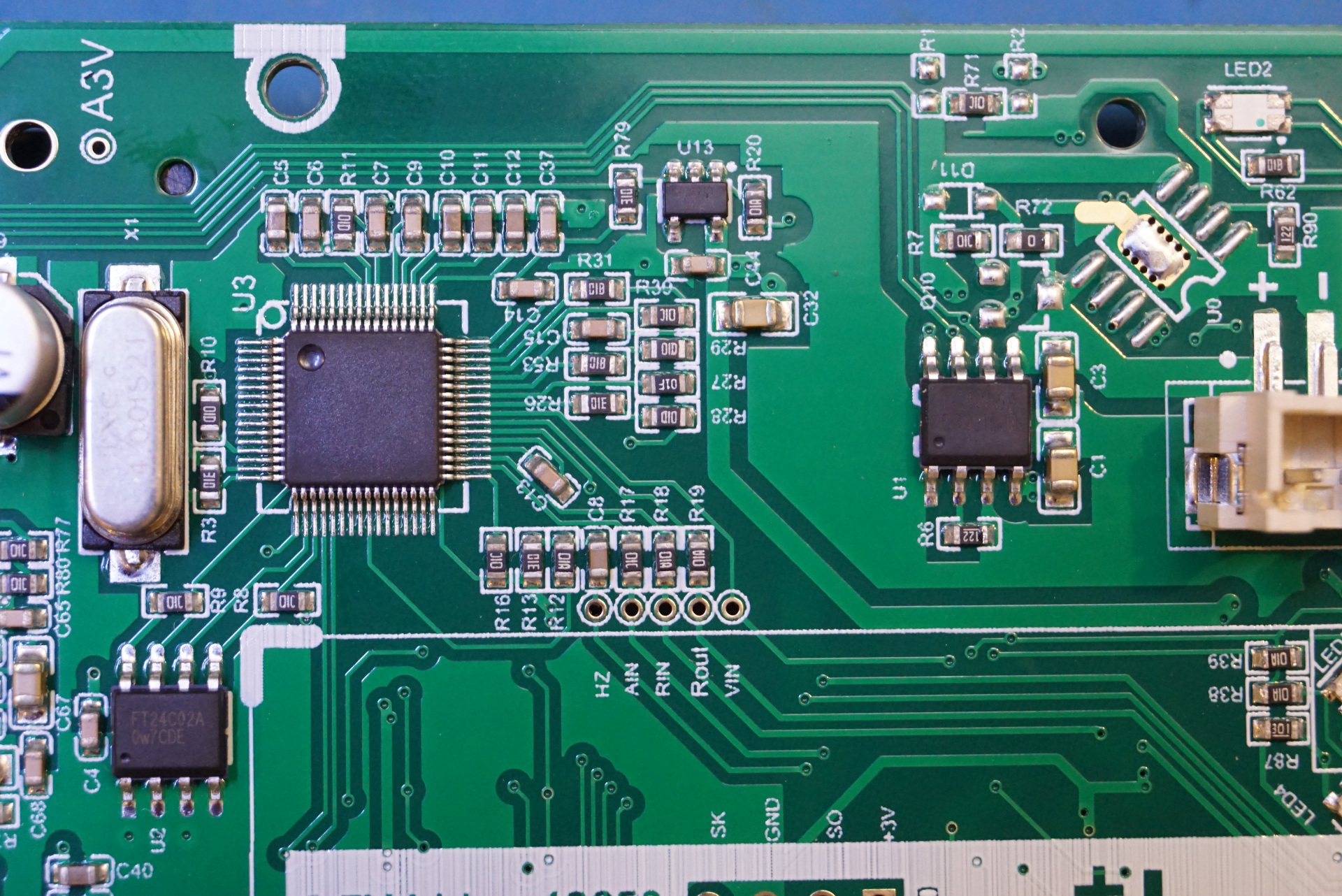
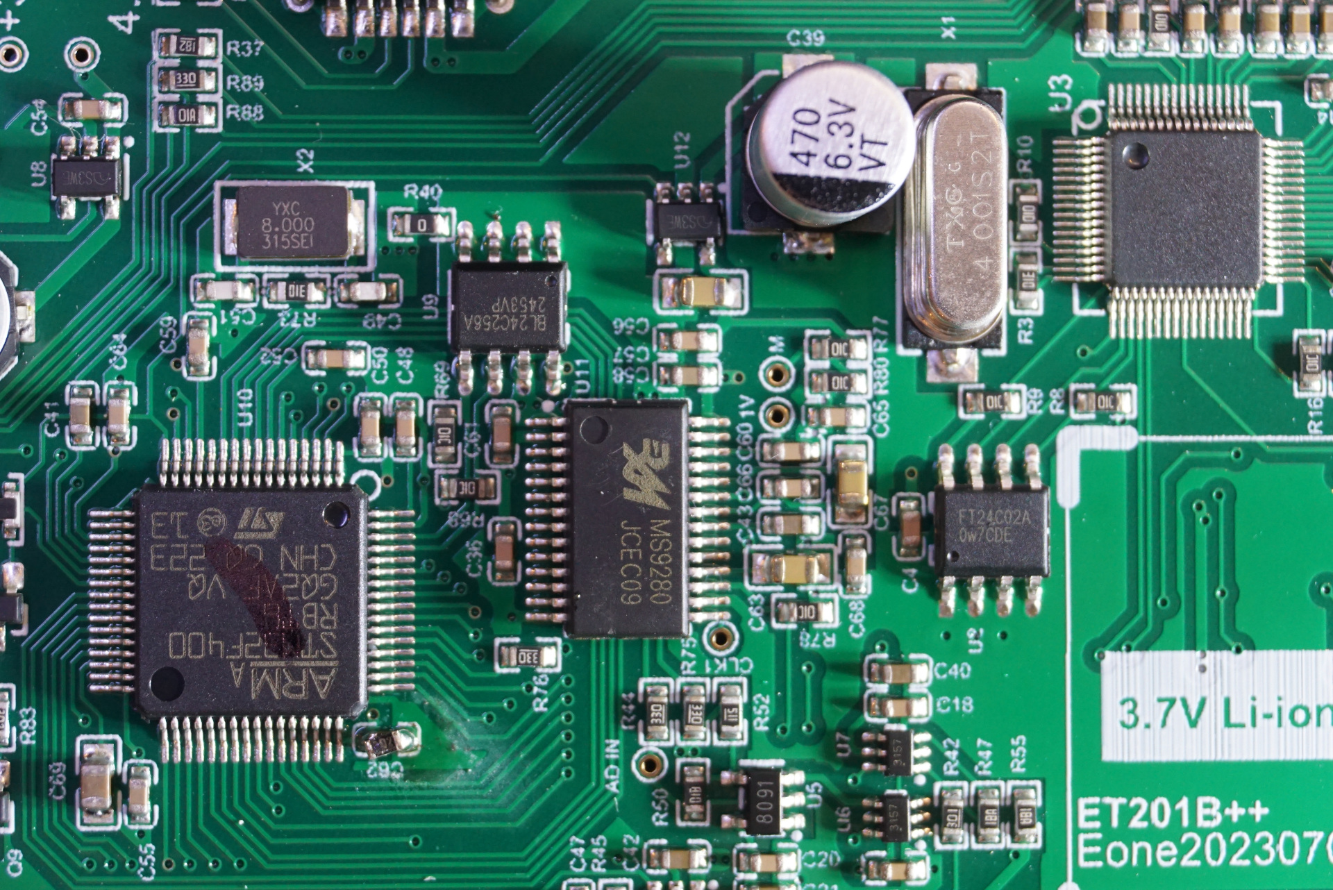
Here is a close up of the MCU section. The main microcontroller used is an ARM STM32F3400. The ADC used is a MS9280 the same 10 bit 50MSPS ADC used in the Zotek ZT-702S.
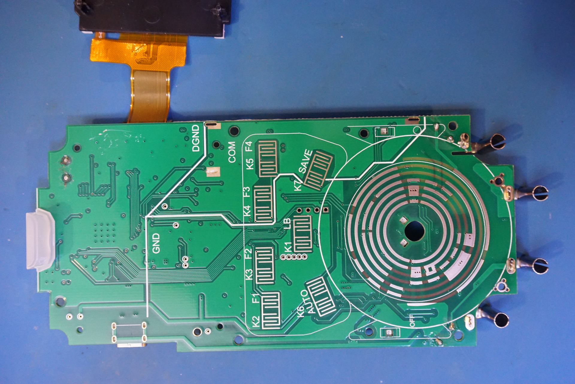
And here is a picture of the reverse side of the board. There are no components on this side. You can see the cutouts for the LEDs mounted on the other side of the board.