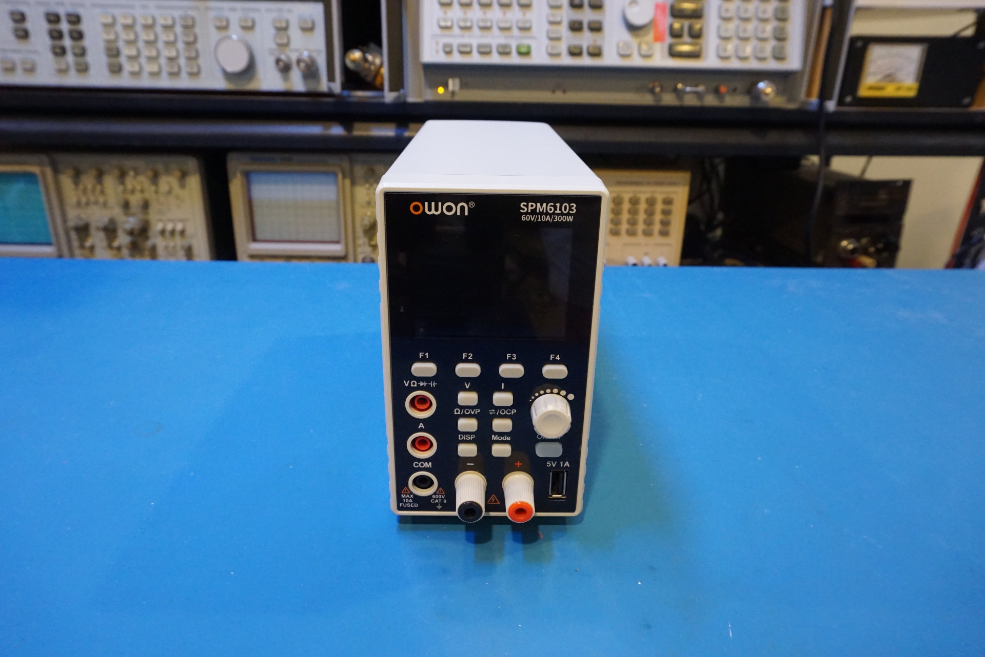
I did a review of an OWON SPM6103 60V, 10A programmable power supply and 20,000 counts DMM all-in-one switching power supply, the review and teardown video is linked below. In this blog post, let’s take a look at some of the teardown pictures.
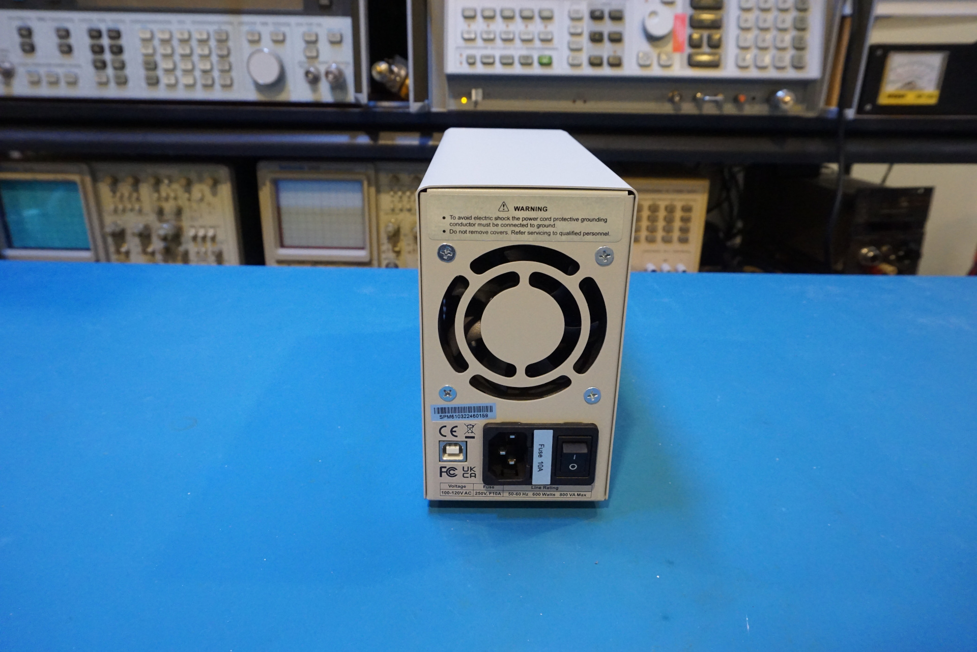
The SPM series power supplies also support PC communications via the USB port located at the back of the unit. The power supply can be programmed remotely by PC software via SCPI as well.
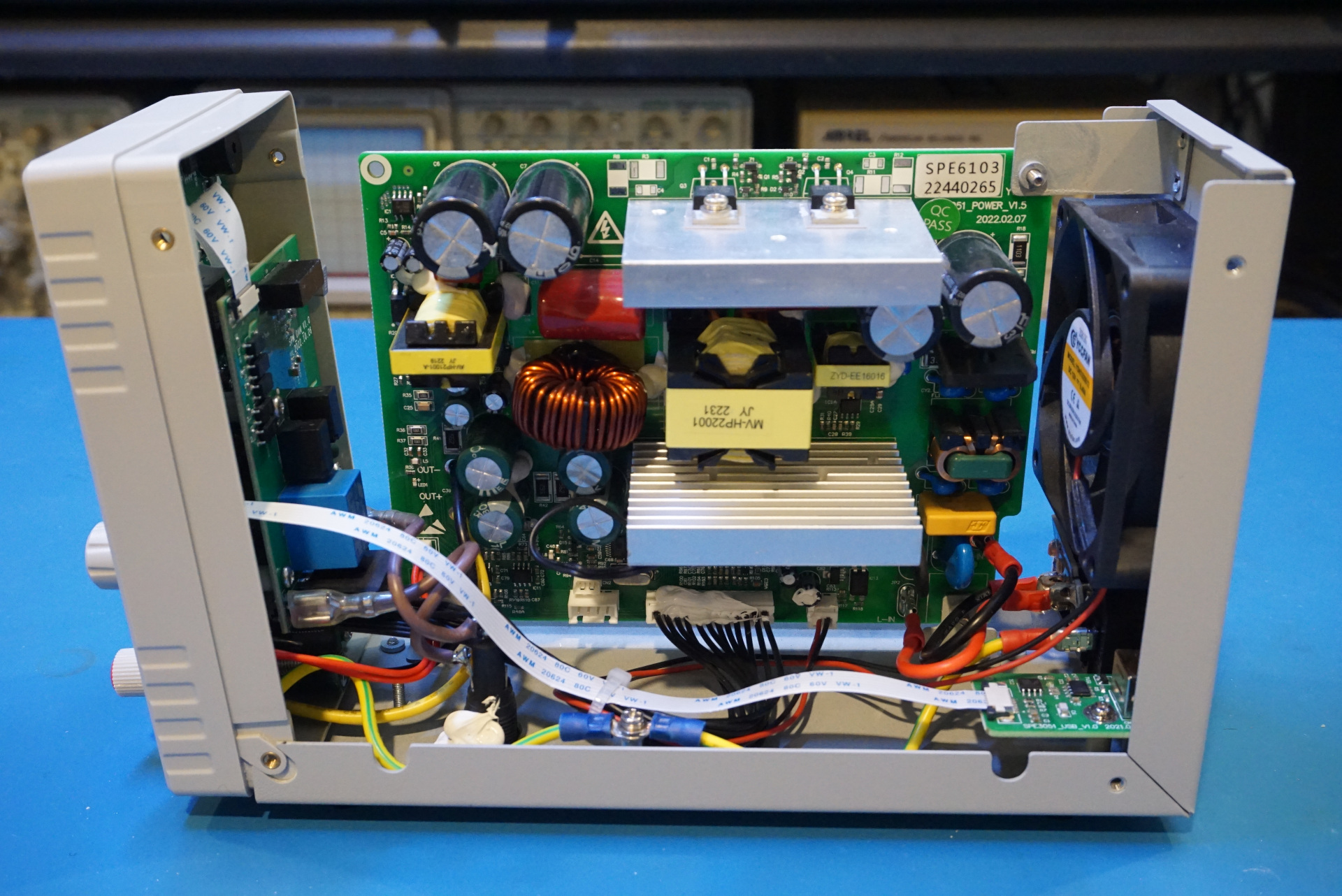
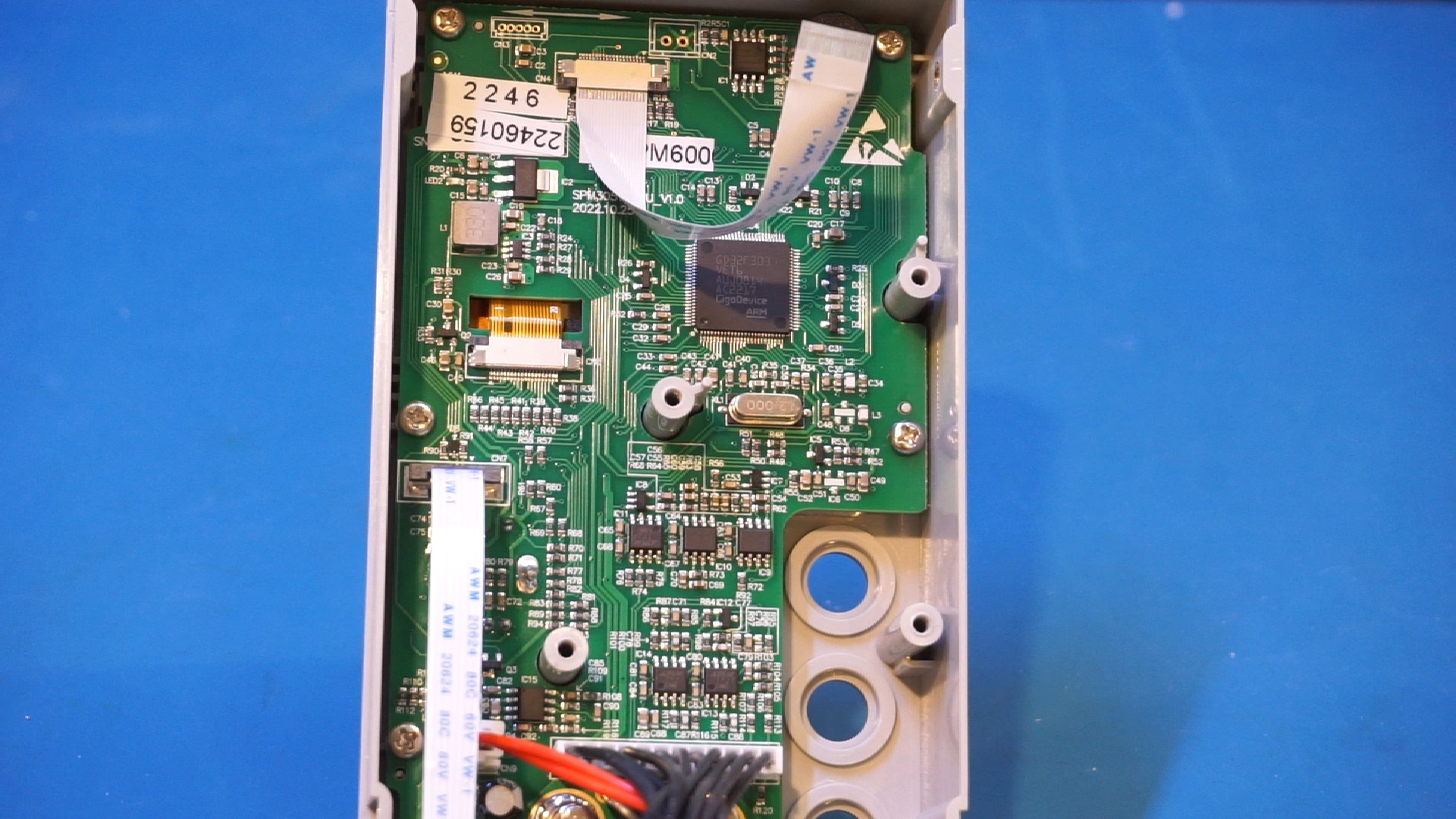
Here are a couple of pictures showing the arrangement inside the power supply once the case is opened.
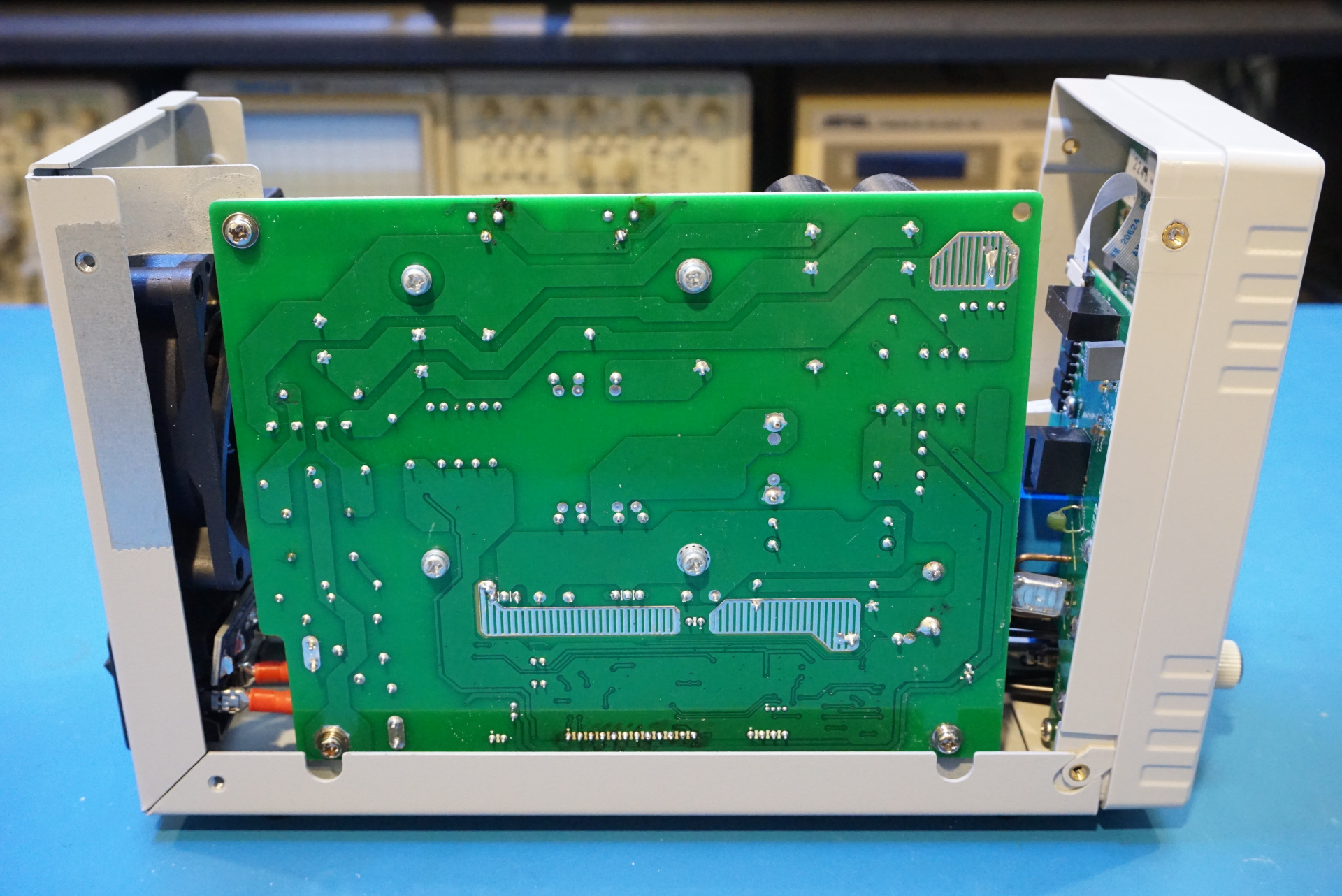
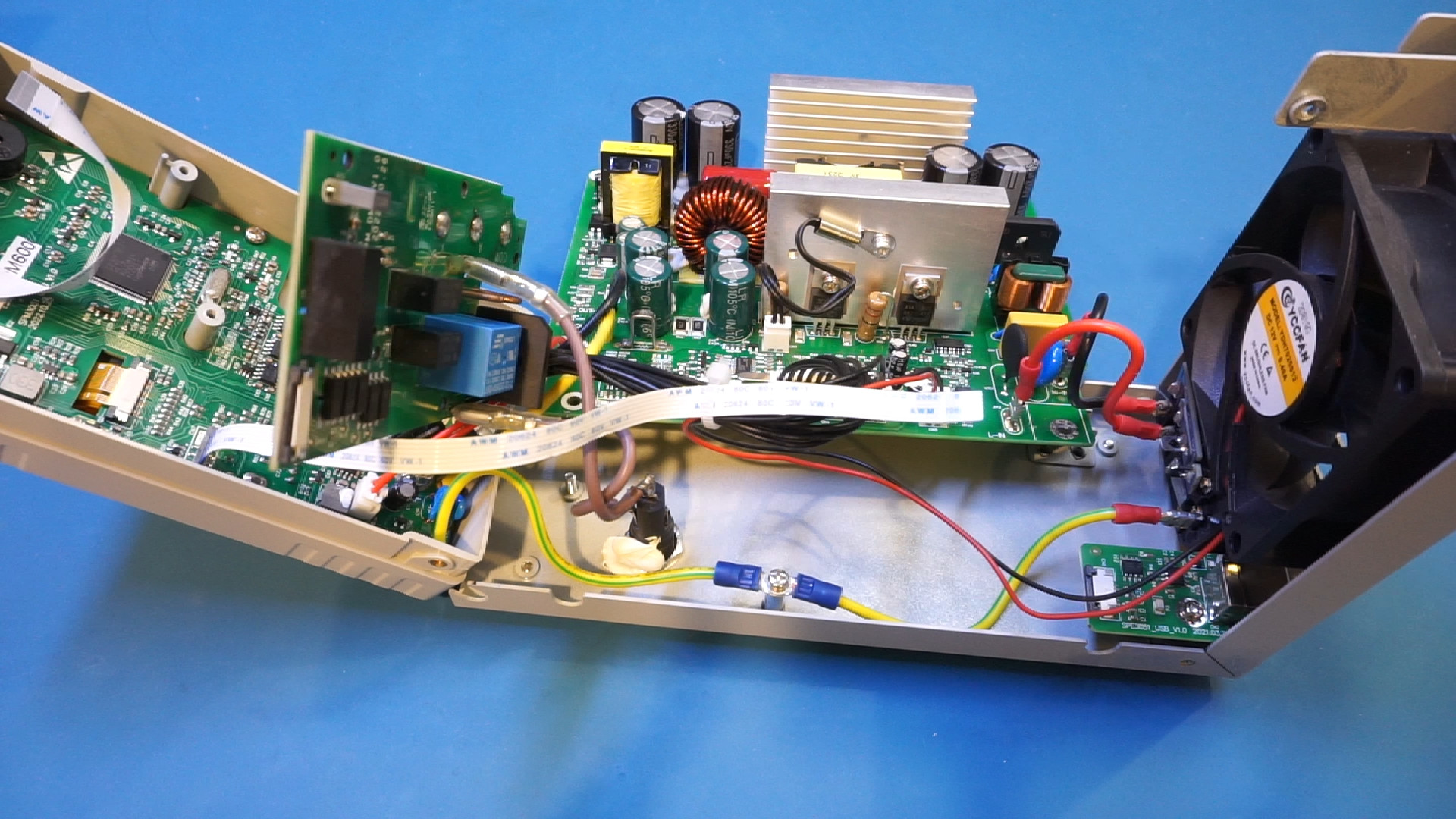
Here is another view with the boards further dissembled.
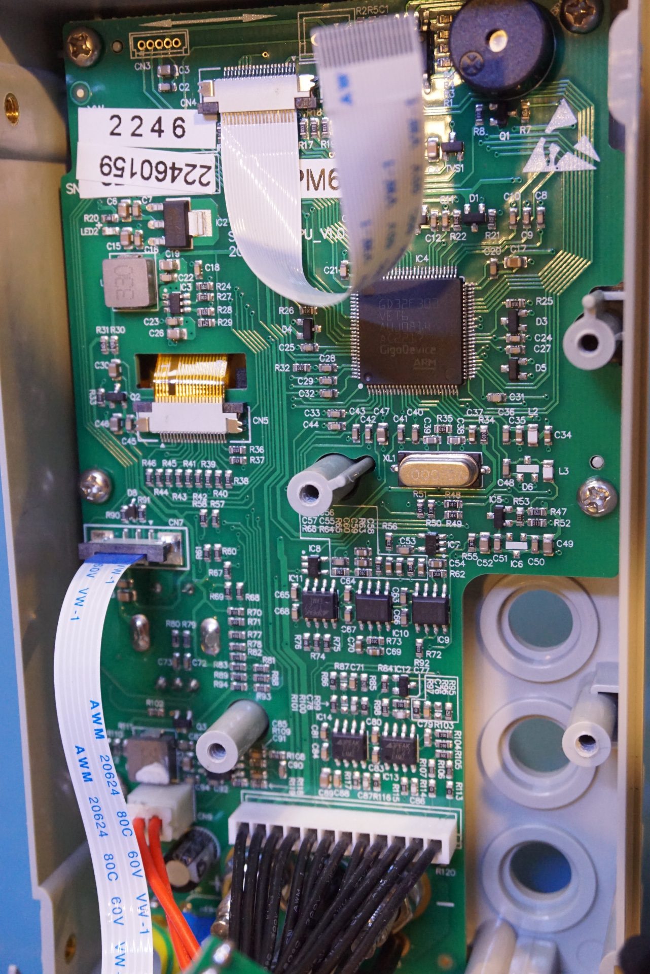
Here are a couple of pictures showing the front panel PCB. the PCB has the marking SPM600 on it, so it looks like this PCB is different than the one used in the SPE series which are without the DMM sections. The front panel uses the ubiquitous GD32F303VET6 ARM Cortex-M4 microcontrollers from GigaDevice.
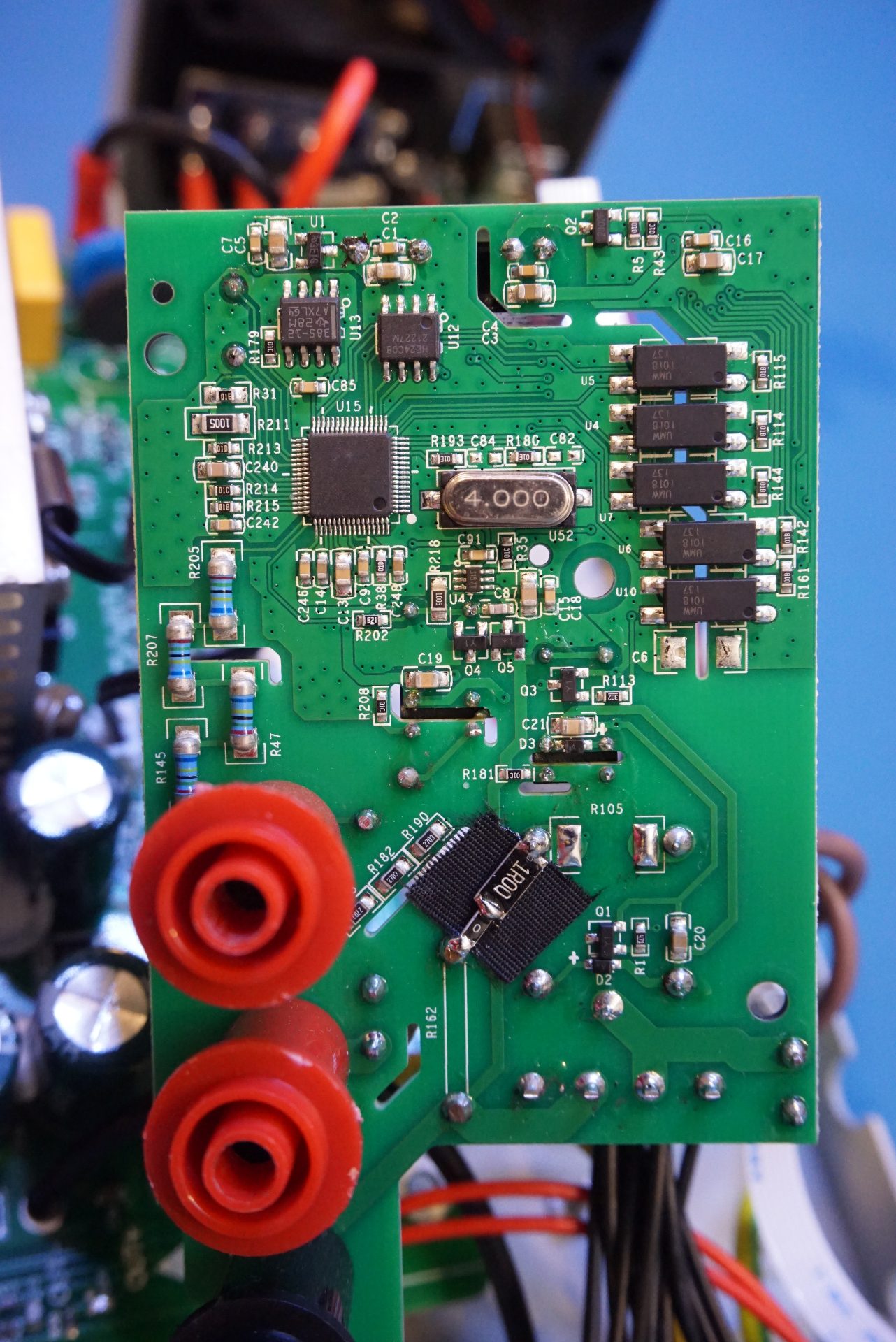
Here are a couple of pictures of the DMM daughter board. Unfortunately the markings on the multimeter chip was removed so I do not know which chip is used. But needless to say, it is a 20,000 counts chip. The bodged resistor is the current shunt for the mA range measurement. The voltage reference used here is an LM385-1.2.
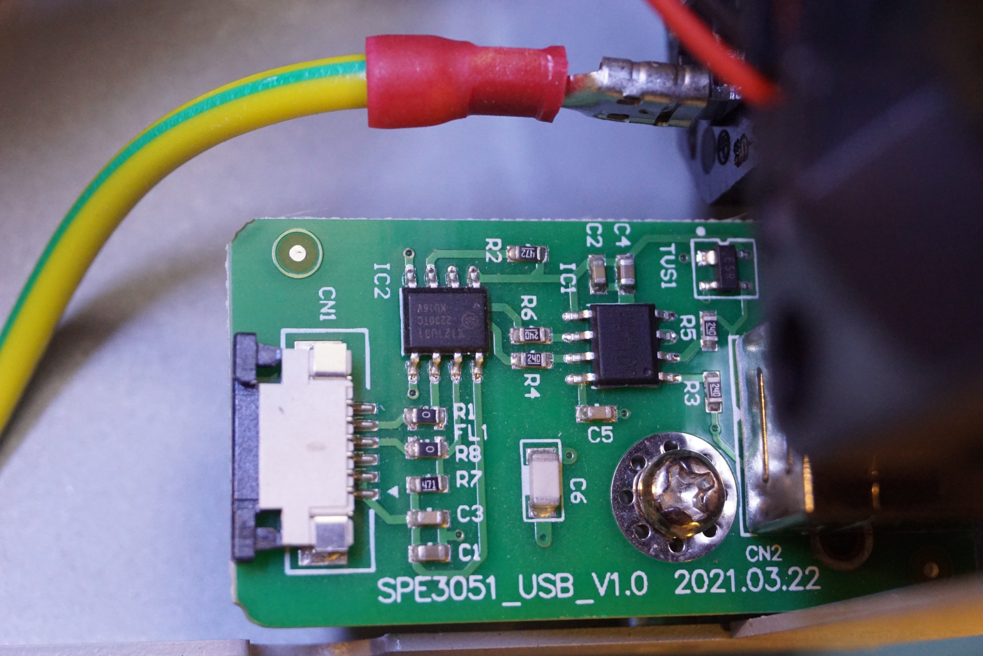
Here is a close up of the USB board that is responsible for handling PC communications. The USB port is fully isolated via the π121u31 isolater from 2Pai Semi. And the USB to UART chip used here is a CH340.
The picture below is the main switching power supply board. It consists of the main power supply circuitry and an auxiliary power supply.
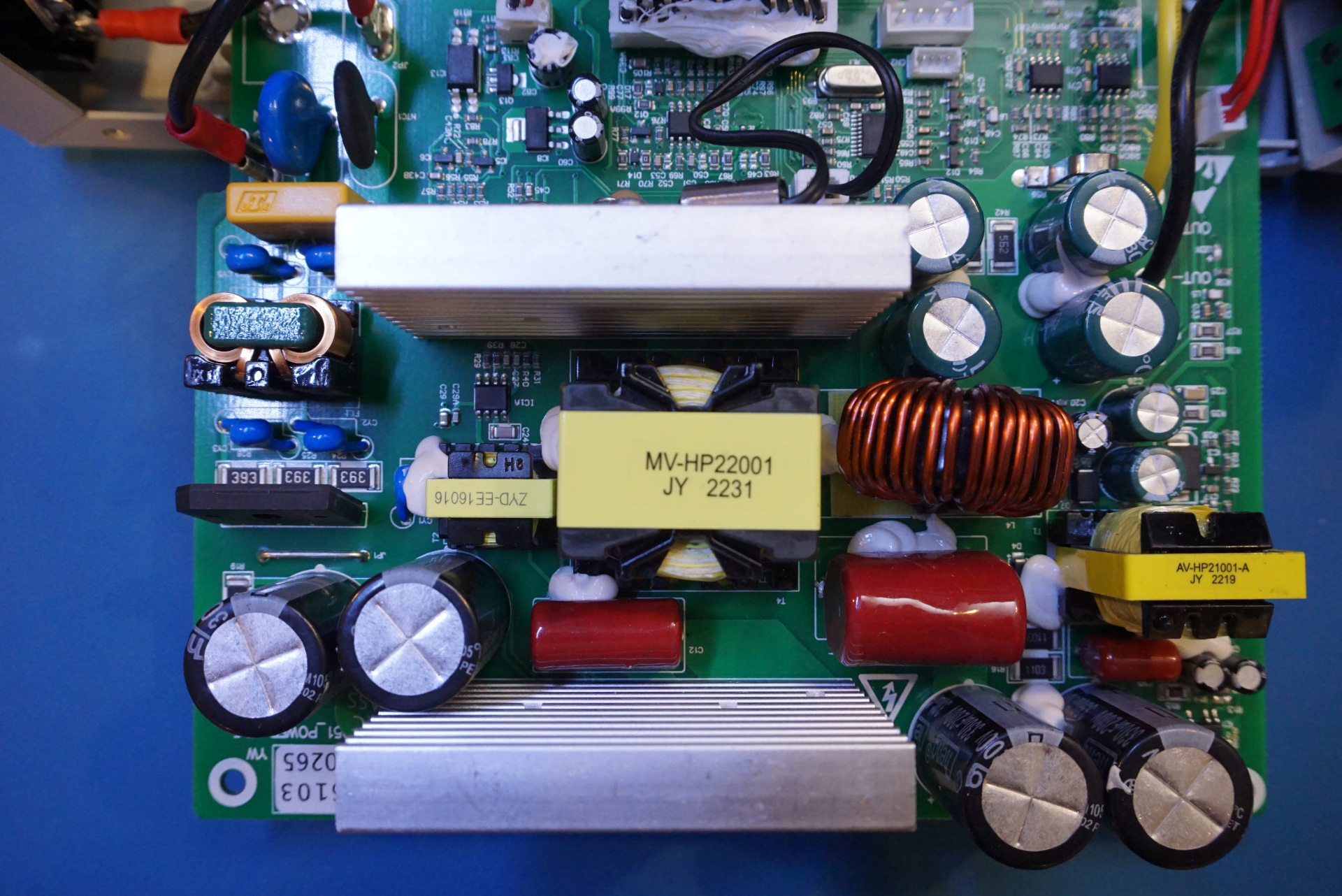
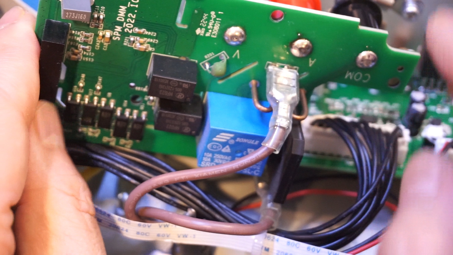
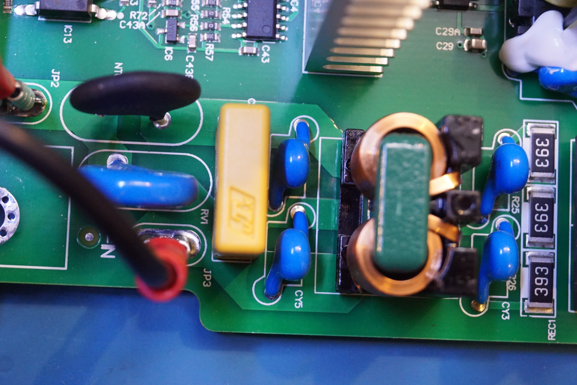
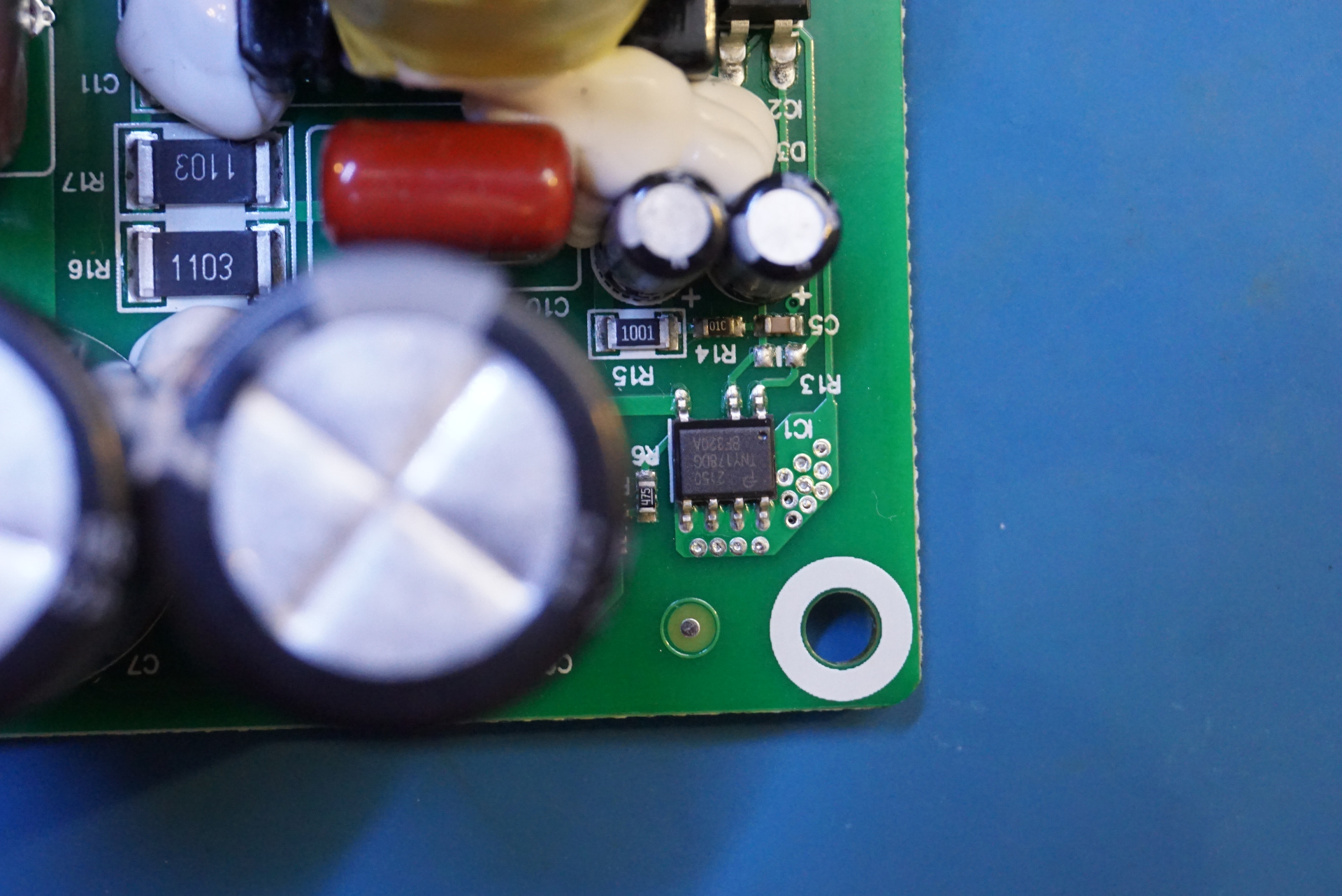
In the picture to the left below you can see the input protection and filtering section of the power supply. The common mode choke used is a flat wire one which allows higher current for similar sized component. The auxiliary power is provided by the TNY178 offline switcher.
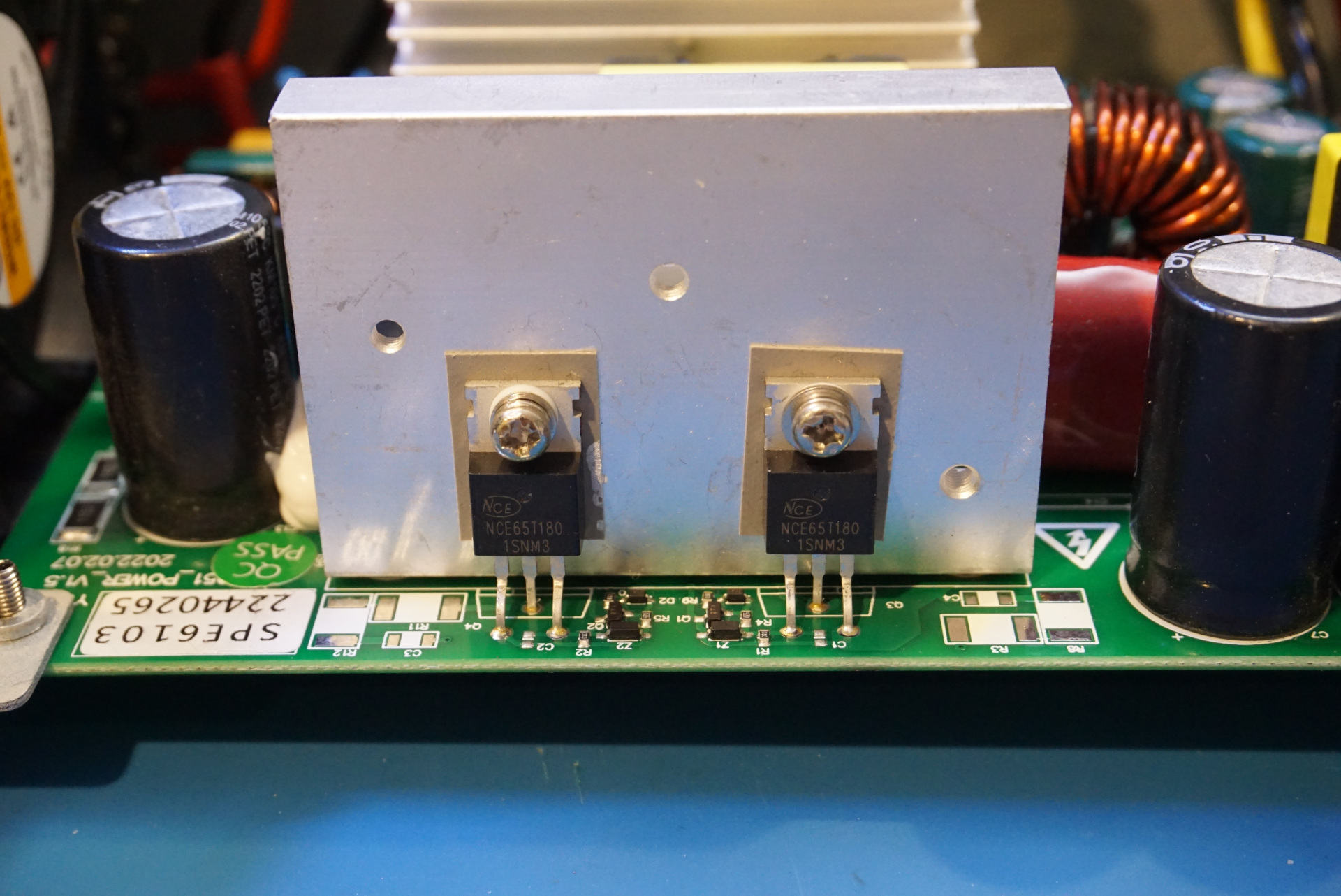
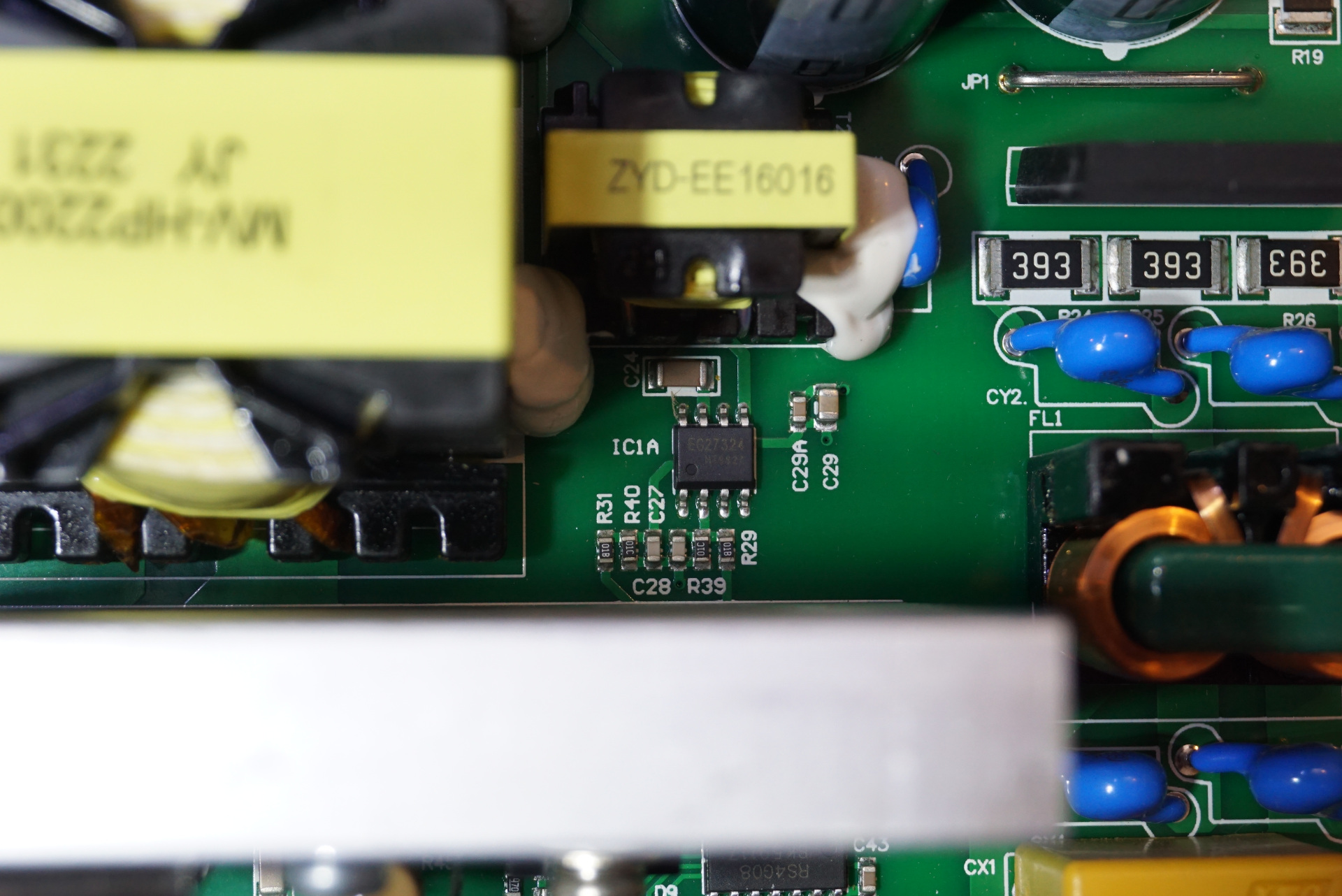
The main power supply is switched by two N-channel MOSFETs NCE65T180 in a push-pull configuration. It is driven by a standard dual channel MOSFET driver chip EG27324. The gate of the high side MOSFET is driven by the smaller pulse transformer as the EG27324 does not have a builtin charge pump for the high side drive.
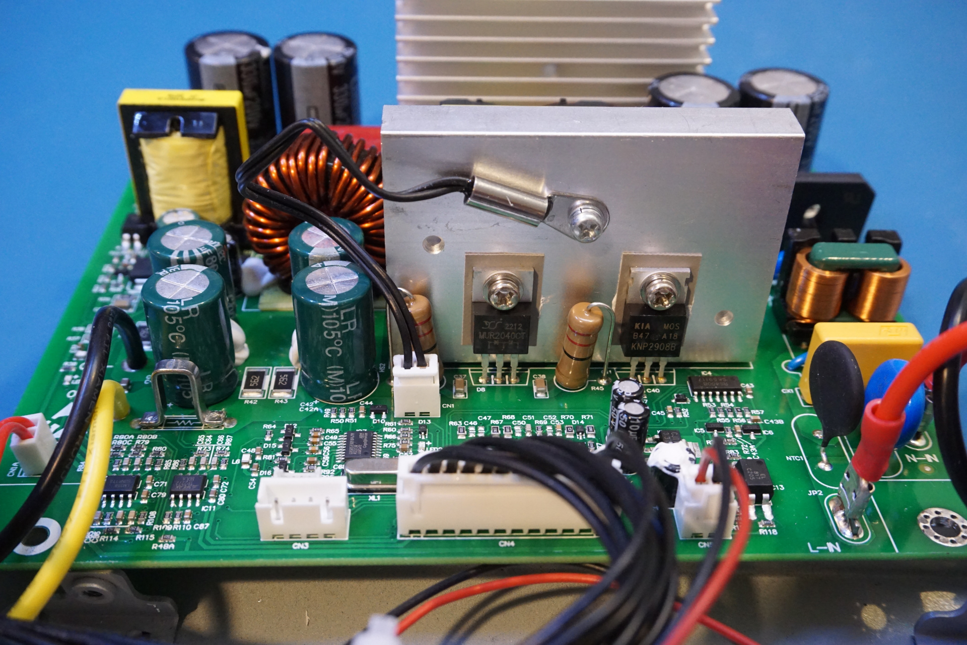
The otuput of the power supply is switched by the KNP2808B MOSFET. On the same heatsink there is a MUR2040CT fast recovery diode pair.
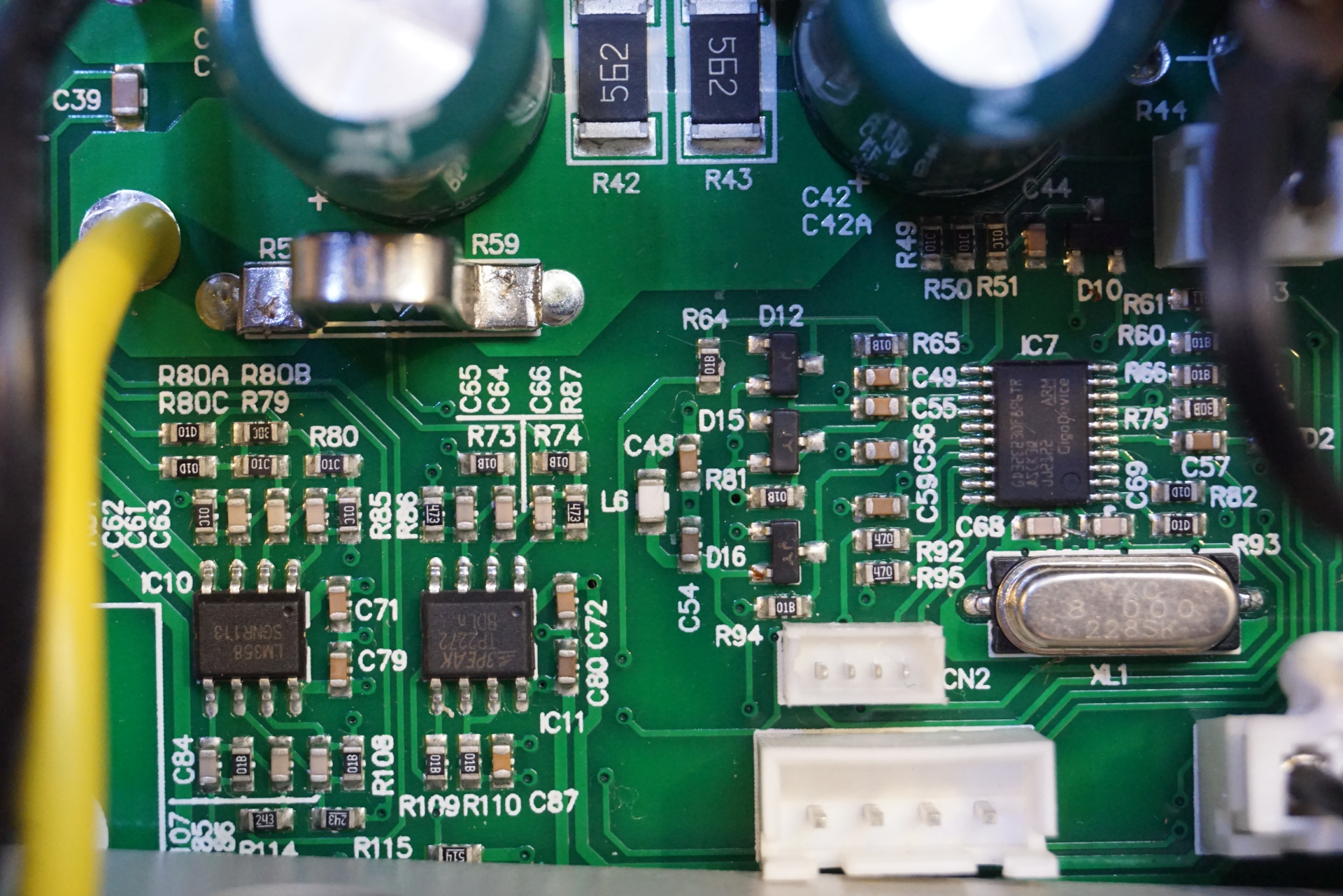
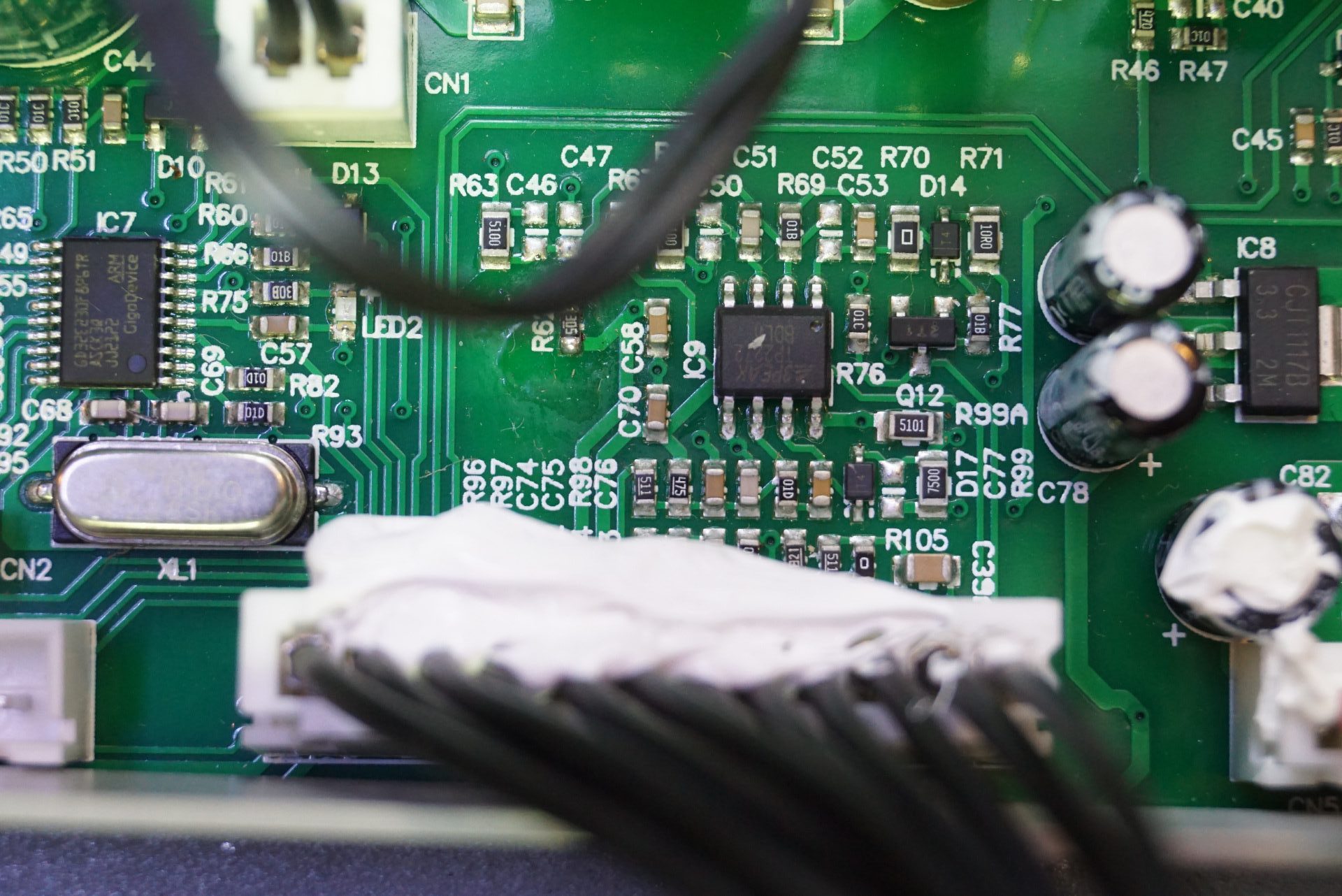
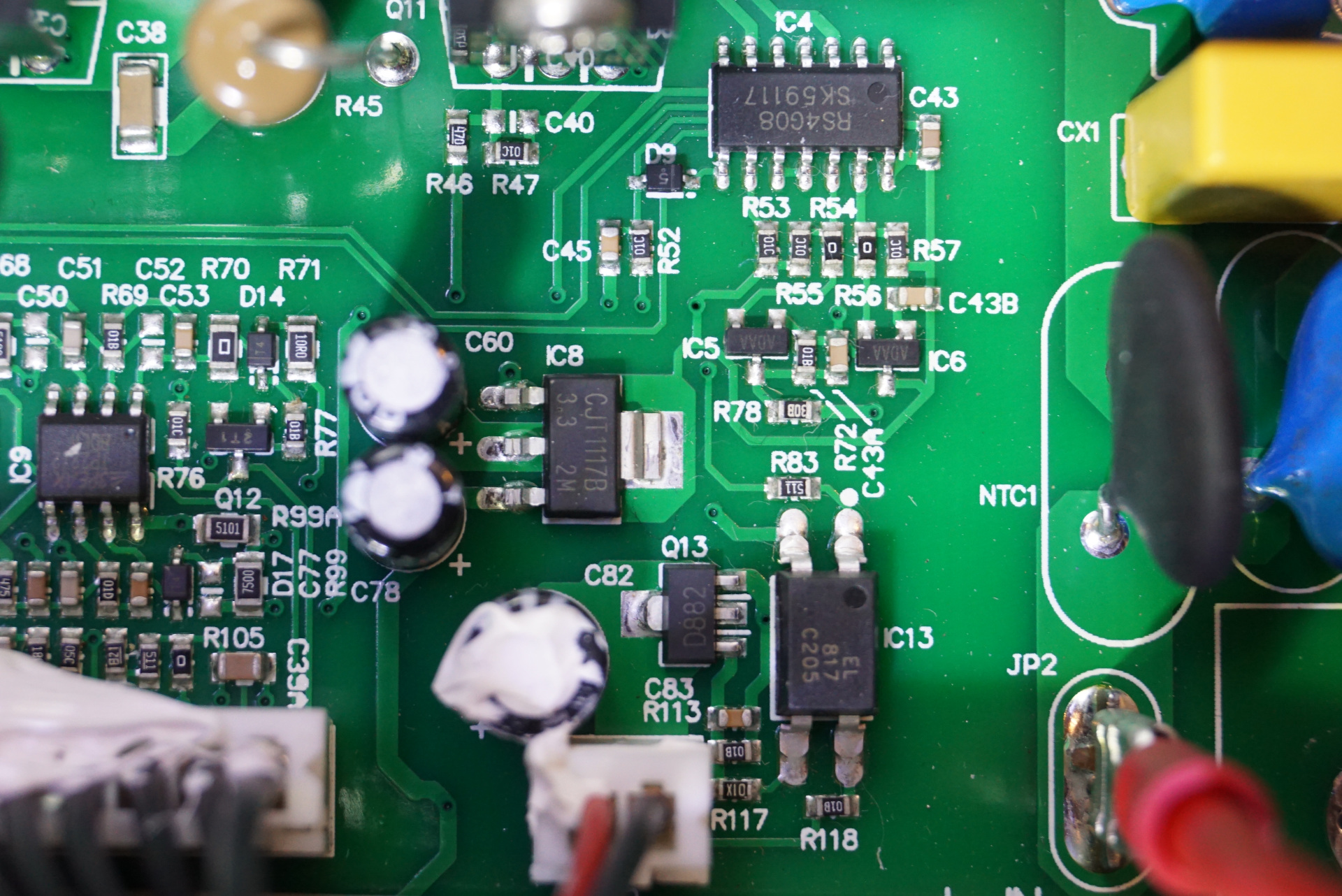
The output current shunt can be seen in the picture above, and in the picture to the left below you can see the same section of the circuit board. There is an LM358 opamp. By the look of it the current shunt voltage is amplified by the TP2272. You can also see the main microcontroller used in this power supply. It is a GD32E230F, GigaDevice’s entry-level ARM Cortex M23 MCU,
It looks like there is another TP2272 rail-to-rail output opamp in the middle picture below. In the picture to the right, you can see an additional TP2272. There is also a 3.3V regulator. The 14 pin SOIC towards the top is an RS4G08 quad 2-input AND gate.