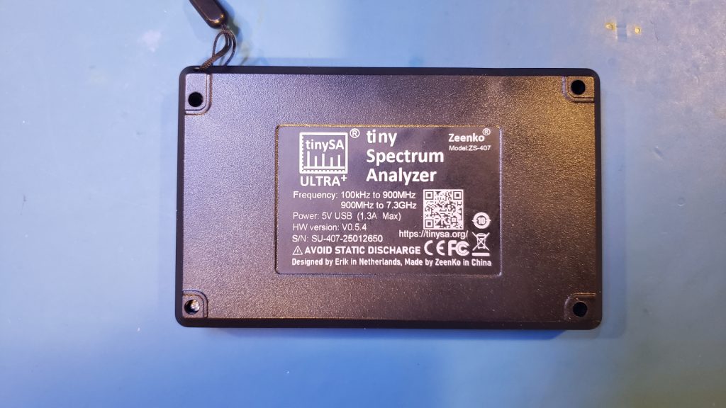
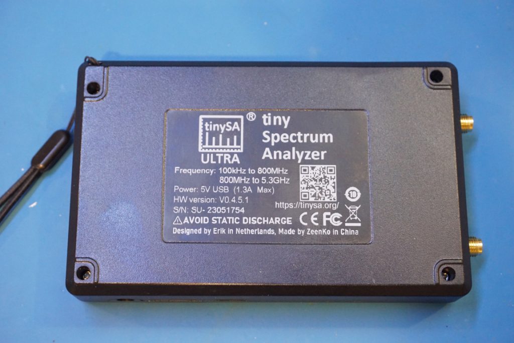
A couple of years ago, I did a review and teardown of a tinySA Ultra spectrum analyzer. That tinySA Ultra was a ZS-405. I recently got my hands on an upgraded version — the ZS-407, and in this blog post, I will compare some of the teardown pictures with those of the ZS-405. For an in-depth review and teardown of the tinySA Ultra+ ZS-407, you can check out the video below:
The ZS-407 can measure signals with a frequency range between 100 kHz and 900 MHz in standard mode, which is 100 MHz higher than the ZS-405. With Ultra mode enabled, the ZS-407 is level calibrated up to 7.3 GHz, which is 2 GHz higher than the ZS-405. The ZS-407 can observe signals up to 12 GHz. Although ZS-405 can also do that using the same 3rd harmonic mode, the main difference is that the ZS-407 has much higher sensitivity so the observed signal should have better signal to noise ratio (SNR).
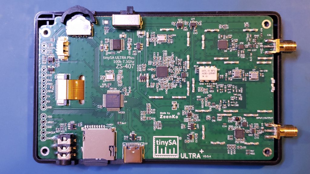
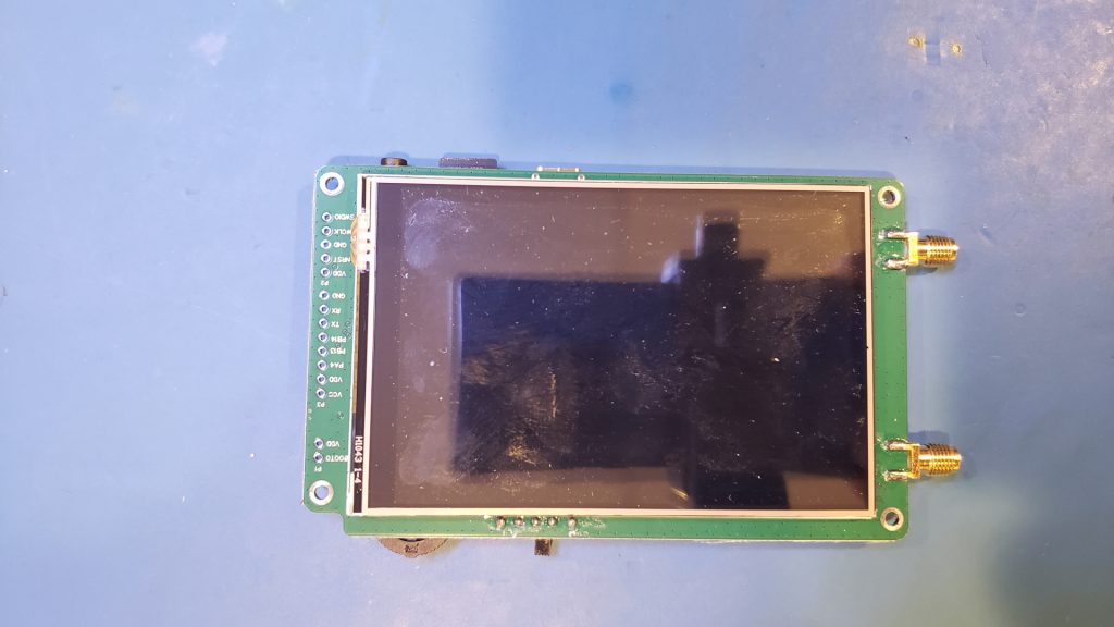
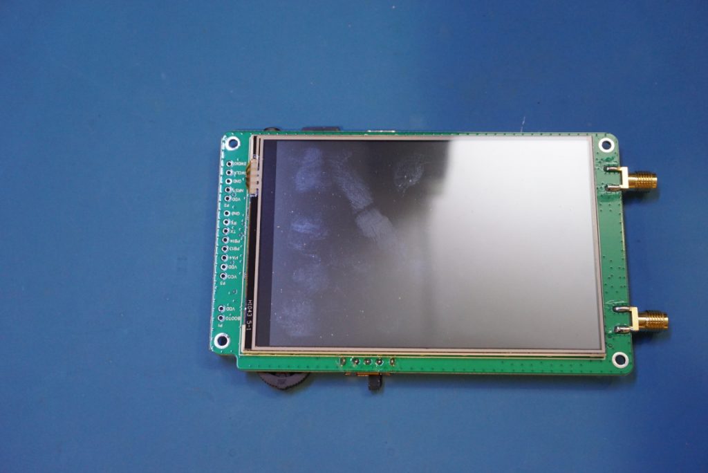
From a glance, the circuit board layout is pretty much identical between these two different models. The only major difference you can see in the pictures below are the LCD connectors. The LCD module used in the ZS-407 has fewer pins compared to the LCD module used in the ZS-405.

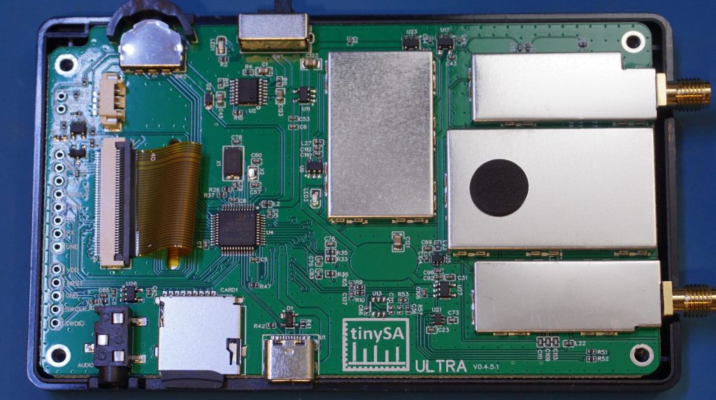
Here are a couple of pictures showing the circuit boards of ZS-407 and ZS-405 with the shielding cans removed:
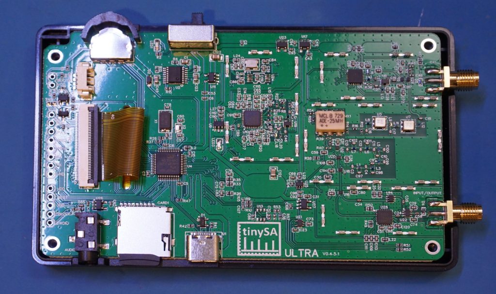
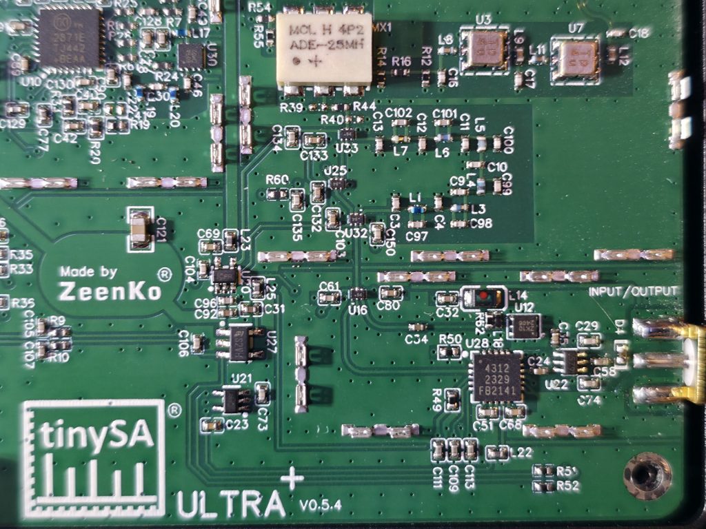
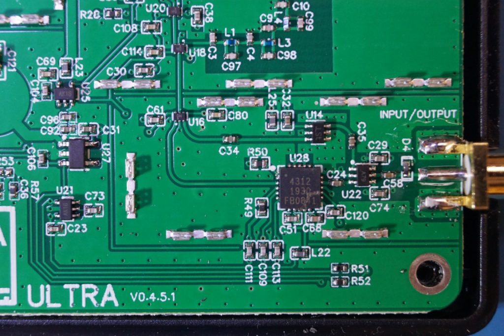
The pictures below are the RF input/output sections from ZS-407 and ZS-405. The chip marked 4312 is a PE4312 6-bit RF digital step attenuator chip.
Interestingly the 4312 is only rated up to 4 GHz, but the the operating frequencies of either ZS-405 or ZS-407 is up to 12 GHz. So clearly, there is quite a bit of margin builtin with this attenuator chip, but nevertheless both the ZS405 and ZS407 are using it out of spec when the input frequencies are beyond 4 Ghz.
The LNA used in these models are slightly different. In the ZS-405 U14 is the LNA, which is a BGA2817 monolithic microwave integrated circuit (MMIC) wideband amplifier. And in ZS-407, the LNA is U12, which is a ZK10 I believe. U22 would be an RF switch.
Here you are looking at the Cal port section of the circuitry. The transceiver chip used are identical between these two models, it is an Si4468. And it is used to further down convert the IF into a manageable sub-MHz IF signal for further processing.
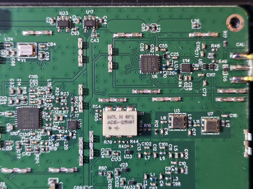
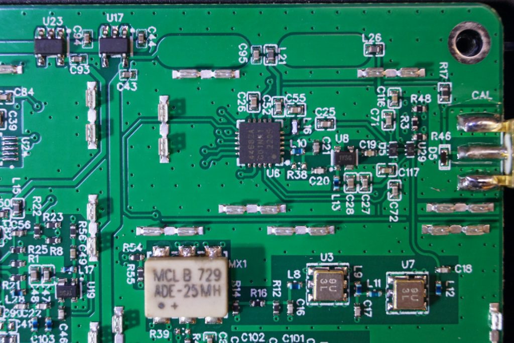
In the above pictures, you can see that the mixers used are also identical between these two models, it is an ADE-25MH which is capable of mixing signals between 5 MHz and 2.5 GHz.
In the two pictures below, you can see the differences in the RF synthesizers used. The RF synthesizer is used to generate the LO used in the tinySA. Because the frequency range differences, the RF synthesizer chip in the ZS-407 has changed to a MAX2871E which can synthesize frequencies up to 6 GHz. This is in contrast to the synthesizer used in the ZS-405, which is an s ADF4350A, and it has an output frequency range up to 4.4 GHz.
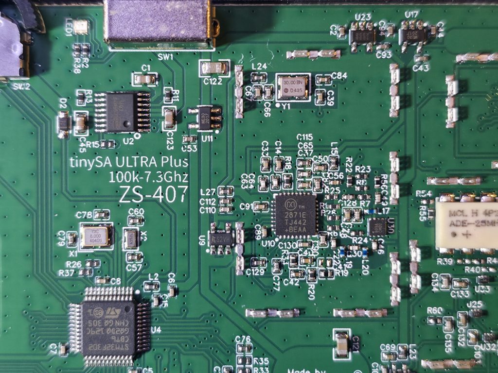

Both models use the same microprocessor. It is an STM32F302, an ARM based Cortex M4 processor.
And below are a couple of pictures showing the LCD side for both the ZS-407 and ZS-405.
In both ZS-405 and ZS-407, the same 5000 mAh Lipo battery is used.
#ad Tinysa Ultra+ 407: https://amzn.to/46KVNI6

