After I wrote this guide on how to build an ultrasonic range sensor from scratch, I have received many comments and questions. A couple of readers have emailed me stating that this sensor works great by itself, but somehow when put onto a robotic platform it sometimes returns random range data.
The most likely cause for this “randomness” is insufficient power filtering. Since the combined gain of the two stage amplifier is quite large, any minute ripple in the power supply will likely be coupled onto the output. In applications where motors are used, the power ripple induced interference could be quite severe to the point that the detected signal is overwhelmed by noise and thus the detected range seems to be random. This is especially true when the motors are PWM controlled.
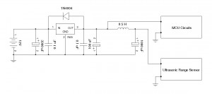
To solve this problem, it is necessary to use a proper LC filter for the ultrasonic range sensor. A typical arrangement is shown here:

In the example above the battery (12V) powers the motors directly. The ultrasonic sensor and other circuits (i.e. additional MCUs) are powered via a +5V regulator. The decoupling LC circuit is placed between the +5V power supply and the ultrasonic range sensor. Using this arrangement the interference from the power supply ripples due to non-resistive load can be virtually eliminated.
The layout of the receiver section of the board also affects the performance of the sensor. Since the output signal from the ultrasonic transducer is very weak, any noise picked up by the connecting cable between the transducer and the amplifier will get amplified as well. It is recommended that the cable length between the receiver and the amplifier be as short as possible. Also use shielded cable if possible.

