In my previous blog post, I did a quick teardown of my HP 8566B spectrum analyzer. In this post, I will discuss how to use a spectrum analyzer like this to demodulate an AM or a FM signal. A video including the theory and a few experiments is linked towards the end.
For AM signal demodulation, it is pretty straight forward. All we needed to do is to use the zero frequency span mode of a spectrum analyzer. When the spectrum analyzer is set to zero-span mode at the carrier frequency of the modulated AM signal, the displayed signal is essentially in the time domain with the amplitude corresponding to the envelope detector’s output, which is the demodulated signal.
But how do we demodulate an FM signal? For spectrum analyzers without the dedicated FM demodulation capability, we can use the slope detector method to do so.
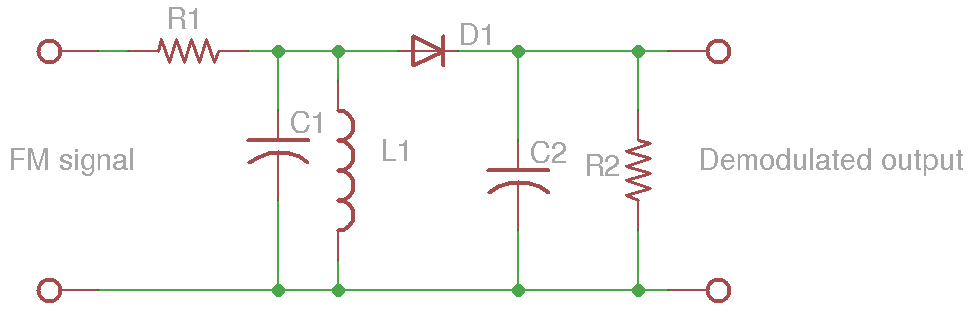
The following diagram shows a simplified slope detector circuit. It consists of a frequency to amplitude converter (which in this case, is a simple tuned LC circuit). Intuitively, when the frequency is near or at the LC resonant frequency of the frequency to amplitude converter, the signal passes through the input resistor without much attenuation. As the signal deviates from the resonant frequency of the LC circuit, the attenuation increases accordingly. Thus the voltage across the LC resonator drops. This way the deviation in signal frequency is translated into the deviation in signal amplitude.
Conveniently, in a spectrum analyzer the resolution bandwidth (RBW) filter serves the purpose of the frequency to amplitude converter illustrated above and by ensuring a sufficiently large resolution bandwidth, we can use either side of the slope to demodulate an FM signal and achieve good linearity.
The video below discusses this top a bit further and shows examples of using the HP 8566B spectrum analyzer to receive AM/FM broadcast signals.

