The last ingredient for my backup power project is an inverter. Since the battery bank I built is a 12V 1.5kWh one, an inverter that can handle a load between 500W and 1000W would be a suitable choice. In theory, all the lights and the refrigerator in my house consume just around 500W. So the 1.5kWh battery bank should be able to power all the essentials for at least a couple of hours in the event of a power failure.
I wanted a pure sine wave inverter as opposed to a modified sine wave inverter since many household appliances and electronics do not play well with modified sine wave inverters due to the high harmonic distortions. After some extensive research, I finally settled on this 12V 800W pure sine inverter made by a little known Chinese company Yueqing Reliable Electric Co. Ltd. The reason is simple, it costs less than $100 and had pretty good reviews on many websites. A better known brand one would easily cost twice or three times as much. For the price, I was willing to give it a try.
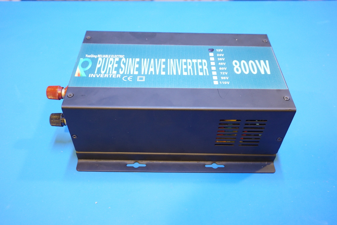
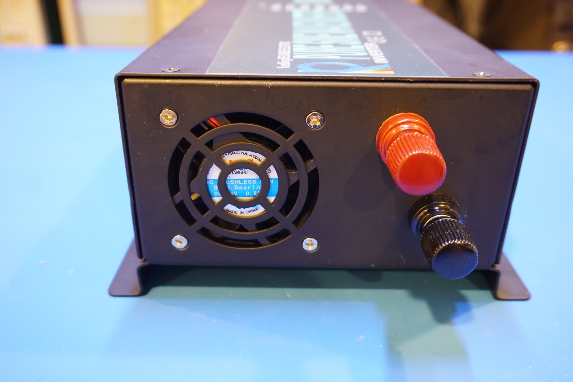
The construction of this inverter looks pretty solid. I like the fact that the positive and negative terminals binding posts are slightly offsetted, as it prevents connecting cables accidentally touching each other and causing a short condition. While the inverter has a cooling fan, it is thermally controlled and only turns on when the internal temperature exceeds certain threshold. So most of the time, the inverter operates silently. During my extensive testing, the fan only turned on when the load on the inverter exceeded 400W and even under maximum load the fan would only operate periodically as needed.
I am not exactly sure what the rating is for the binding posts used. But judging from the dimensions, the threaded brass measures around 5.5mm in diameter which is about 1/3 smaller than the 7.5mm diameter 200A binding post I have. So the current carrying capability should be around 100A, which is more than adequate for the current draw under the maximum load.
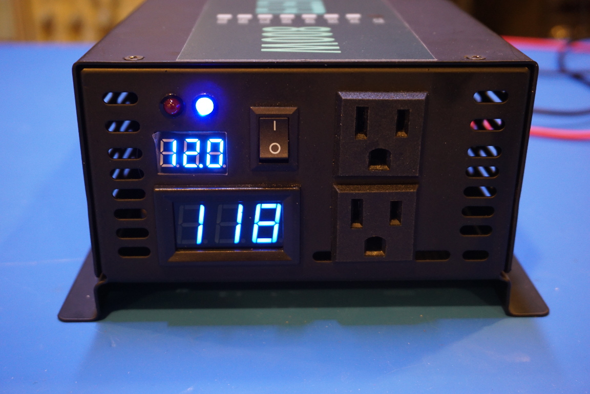
The other side of the panel features two volt meters. One measures the battery voltage and the other measures the output line voltage. There are also a couple of LEDs for status indication. The red LED would come on flashing when over voltage on the input occurs. A high-pitched alarm would sound if the input voltage drops below 9.8V. So for this particular unit the operating voltage range is between 9.8V and 13.5V. The inverter will shut down if the input voltage falls below 9.5V or excceeds 15.5V according to the specifications.
|
|
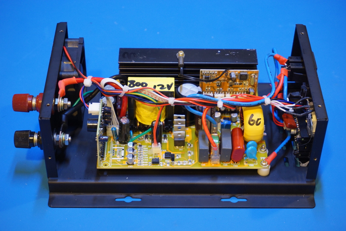
Opening the case is easy. The top cover slid off easily after removing 6 threaded screws. Because this inverter does not use its case as heat sink, it makes servicing relatively easy as the top cover can be totally removed without affecting the operation. As you can see from the picture to the left below, the layout is pretty clean and the wires are neatly tied together.
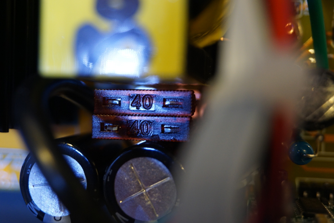
The only gripe I have is the placement of the two 40A fuses. While they are seated in holders, replacing them requires opening up the case which is not very convenient to say the least. But given the built-in protection circuitry, you probably would never have to worry about changing the fuses unless some unaccounted failure mode occurs. By the way, you do get two spare fuses with the inverter.
|
|
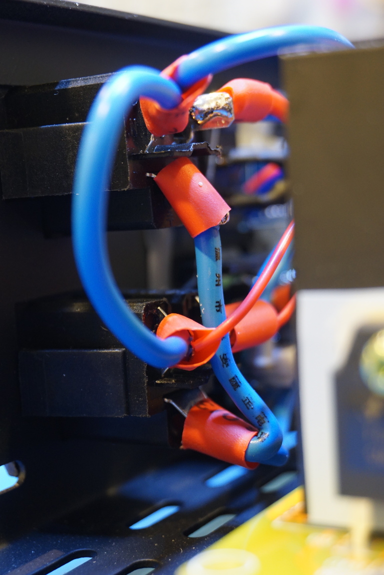
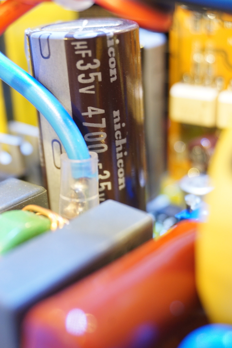
The wiring to the socket could have been made better. The heat shrinking tubing seems to be a bit too short to cover the solder joints. Ideally wiring to the sockets should use disconnects instead of soldering, but it would be more expensive. So if cost has to be cut somewhere, this is the kind of places I wouldn’t mind. And as you can see in the pictures below, all the critical capacitors used are brand-named Nichicon ones and no corners were cut there.
|
|
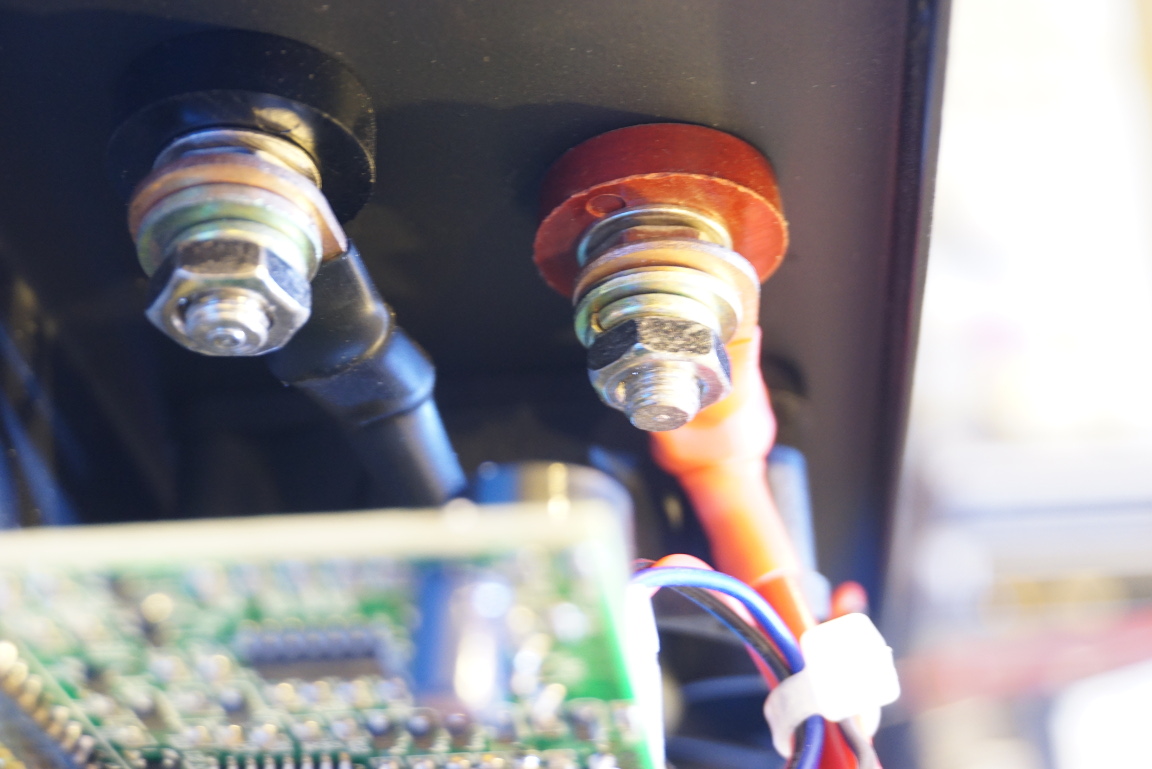
Here towards the left below is a closeup picture of the binding posts connections inside. On the right, you can see two voltage meter modules that are commonly found on eBay. This is another example of how one can lower the cost of a product. Instead of designing your own modules (in this case the voltage meters for the battery and the output), you can simply just incorporate ones that are mass-produced. It seems that many Chinese companies are getting very good at utilizing modular designs.
|
|
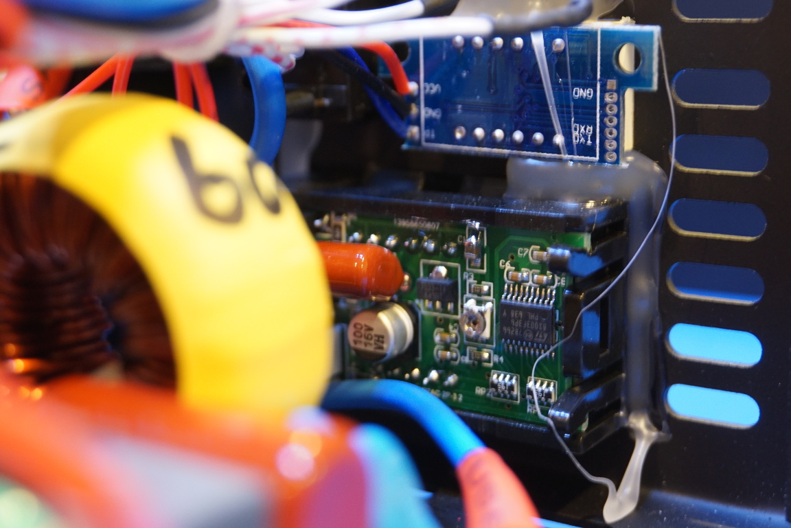
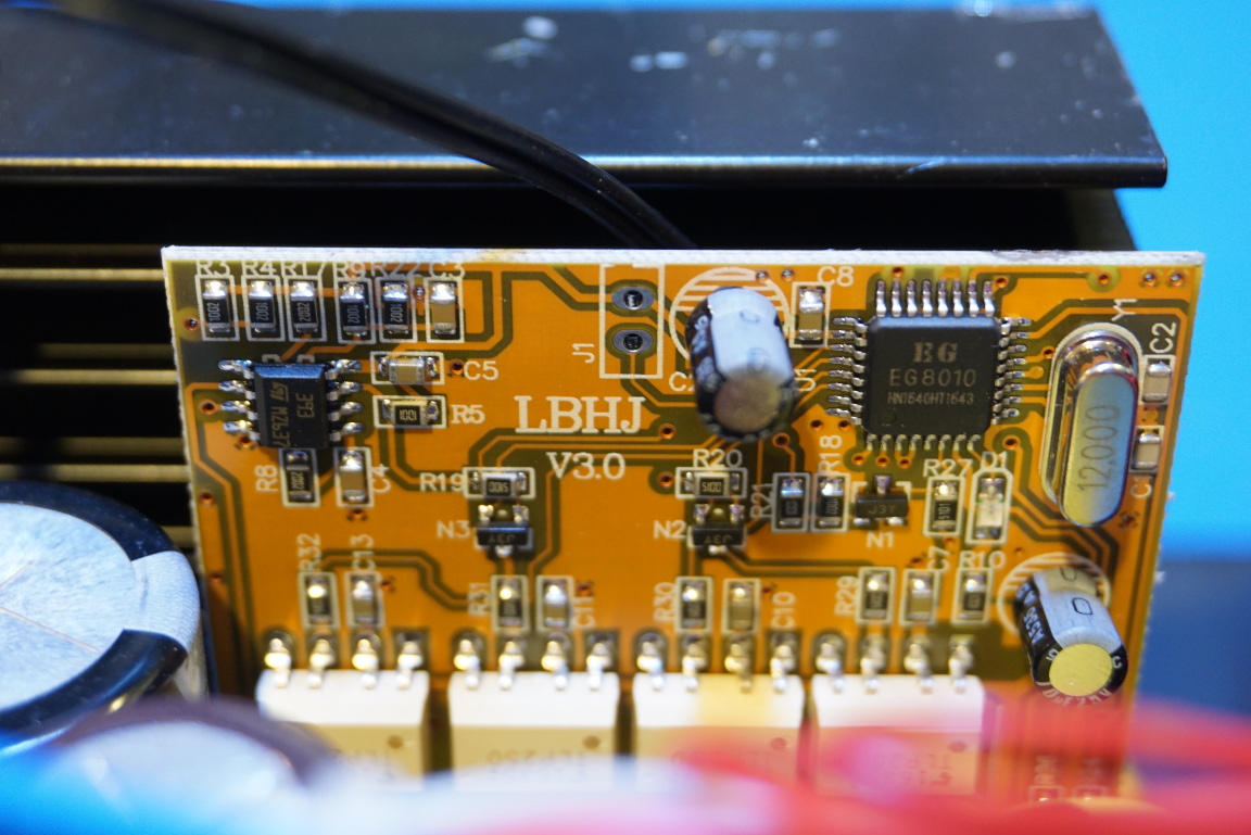
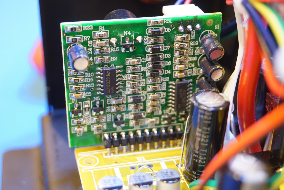
The modular design doesn’t stop there. As you can see the main inverter control is it self a module based on EGMicro‘s indigenous EG8010 pure sine inverter control ASIC. And the other module board is presumably the overload, overvoltage and undervoltage detection board. It consists of a 324 OpAmp and a KA7500 SMPS PWM controller chip.
|
|
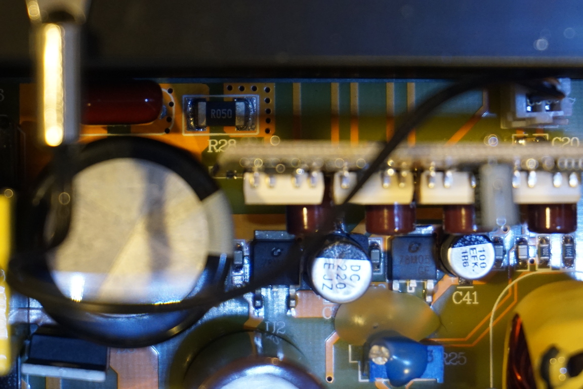
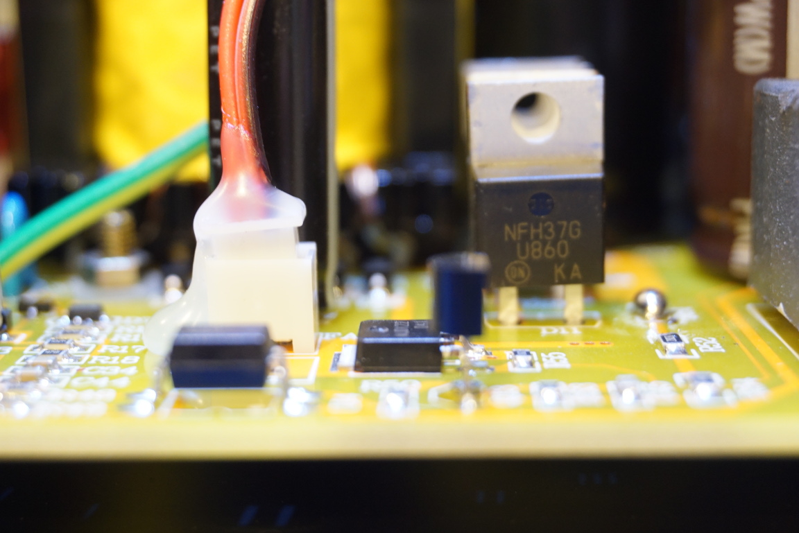
In the picture to the left below, you can see a couple of regulators on the mainboard. The thermistor that is mounted on top of the heatsink also plugs into the mainboard. On the right you can see a group of four MUR860 fast recovery diodes. All PCB’s used in this unit are high quality FR-4‘s.
|
|
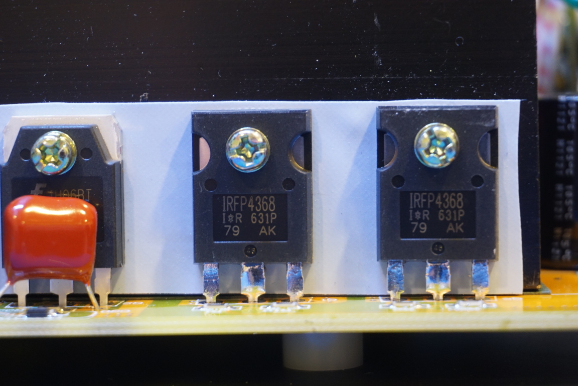
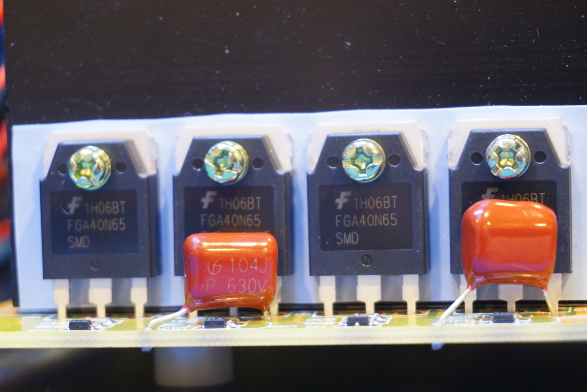
For the DC/DC converter stage, two IRF4368 MOSFETs are used. These MOSFETs have extremely low on resistance (Rds-on, 1.5 mΩ), which translates to lower switching loss and higher efficiency. The DC/DC converter converts the 12V input into 120V (should be 1.414*120=169.7) DC, which is then pulse-width modulated with the on-duration approximating a sine wave. The output bridge for the sine wave PWM modulation utilizes four FGA40N65 IGBT‘s, which are typically more efficient than MOSFETs in switching at higher voltages as in the case of switching the stepped up DC voltage. The PWM waveform is then filtered through an LC low pass filter (via the large toroidal choke and the film capacitors on the main PCB) to produce the final sine wave output.
|
|
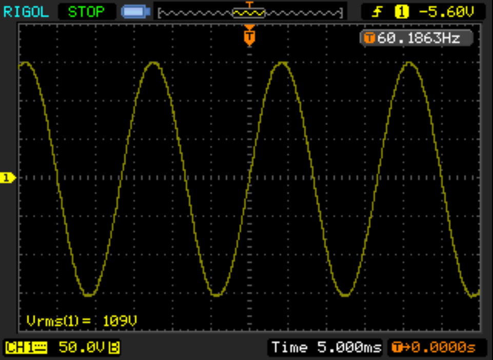
I measured the 120V AC output waveform when no load is attached. The measured sine wave is shown below. As you can see, the sine wave is very clean. Note that the voltage readings below are roughly 10% off due to the extra resistor placed between the probe tip and the output socket for added protection.

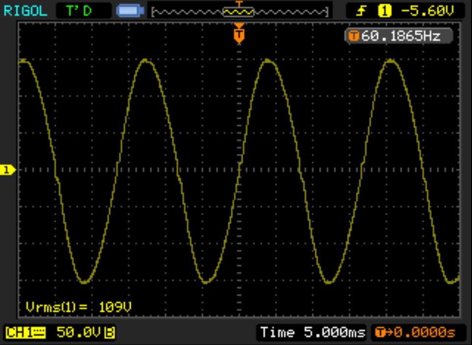
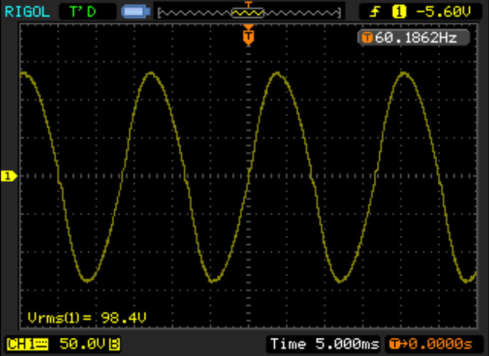
The following two oscilloscope captures show the waveforms when the inverter is under load. The one on the left shows the waveform when the load is 200W. And the one on the right shows the waveform at 400W. Again, the waveforms are quite clean although there is a tiny bit of distortion around zero crossing when the load was increased to 400W. The load I used in the load testing was a resistive heater with the power consumption adjusted using a VARIC (autotransformer).
|

|
As the load increases, the distortion becomes more noticeable. Here are two oscilloscope captures showing when the load was at 600W and 750W respectively. Even at near the full load, the waveform quality remains quite acceptable. The output line voltage remained stable under load and only dropped to just below 110V when the load was increased to 750W.
I wasn’t able to test the inverter all the way up to its rated 800W load however as somewhere beyond 770W the inverter would enter overload protection mode. So the 800W rating clearly is pretty tight with little or no margins. The inverter was able to handle loads with high surge current however. The rated surge capability is 1600W and I had no problem of running an electric drill or a large electric motor.
|
|
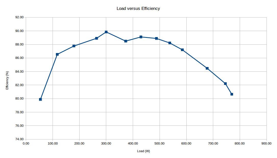
Here is a plot of the measured efficiency numbers with different loads. Although it is less than the spec’d >90%, the efficiency remains pretty remarkable. When idle, the inverter draws just above 600mA. As the load increases, the efficiency quickly improves. With a load between 100W and 650W the achieved efficiency is easily above 85% and it reaches 90% when the load is around 300W.
So, all in all the Reliable Electric 800W inverter seems to be a well engineered quality product and it comes at a very affordable price as well.
In a somewhat lengthy video below, I discussed the operation principle of a modern sine wave inverter and performed some rather comprehensive testing on this 800W pure sine inverter.

