In this blog post, let’s take a look at what’s inside an Extech 380460 miliohm meter.
This is a highly specialized instrument, all it does is measuring low ohm range resistance (from 200mΩ to 2000Ω in five ranges) and nothing else. The meter came with a rugged case which is handy for field use, although its portability is hampered by the requirement of a wall outlet.
Since this meter is designed for low resistance measurement, it came with a set of 4 wire Kelvin clips. The stock leads are not my favorite though, as the design uses rubber rings to hold the two clip pieces together. One issue of this (instead of proper spring tensioned clips) is that the tension is quite weak and it is difficult to make secure contact with small dimension leads. Also, the rubber ring is likely to lose tension and fail over repeated use.
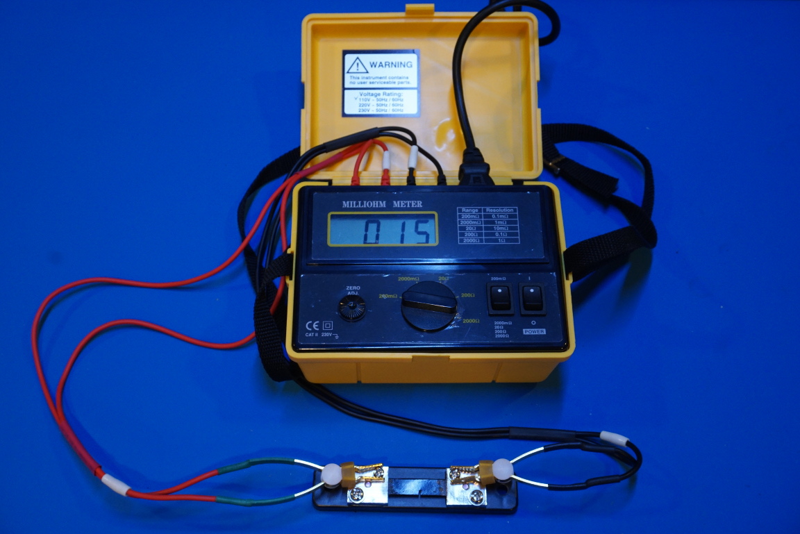
According to the specifications, Extech 380460 has a 3½ display and in its 200mΩ range, it has a resolution of 0.1mΩ. The test current for this range is at 100mA, which is significantly higher than the current used for resistance measurements for most multimeters. My Keithley 196 benchmeter for instance, also has a 0.1mΩ resolution in its 300Ω range, but the measurement current is only at 1.7mA. The higher test current increases the voltage drop across the DUT and reduces the noise pickup in the corresponding voltage measurements.
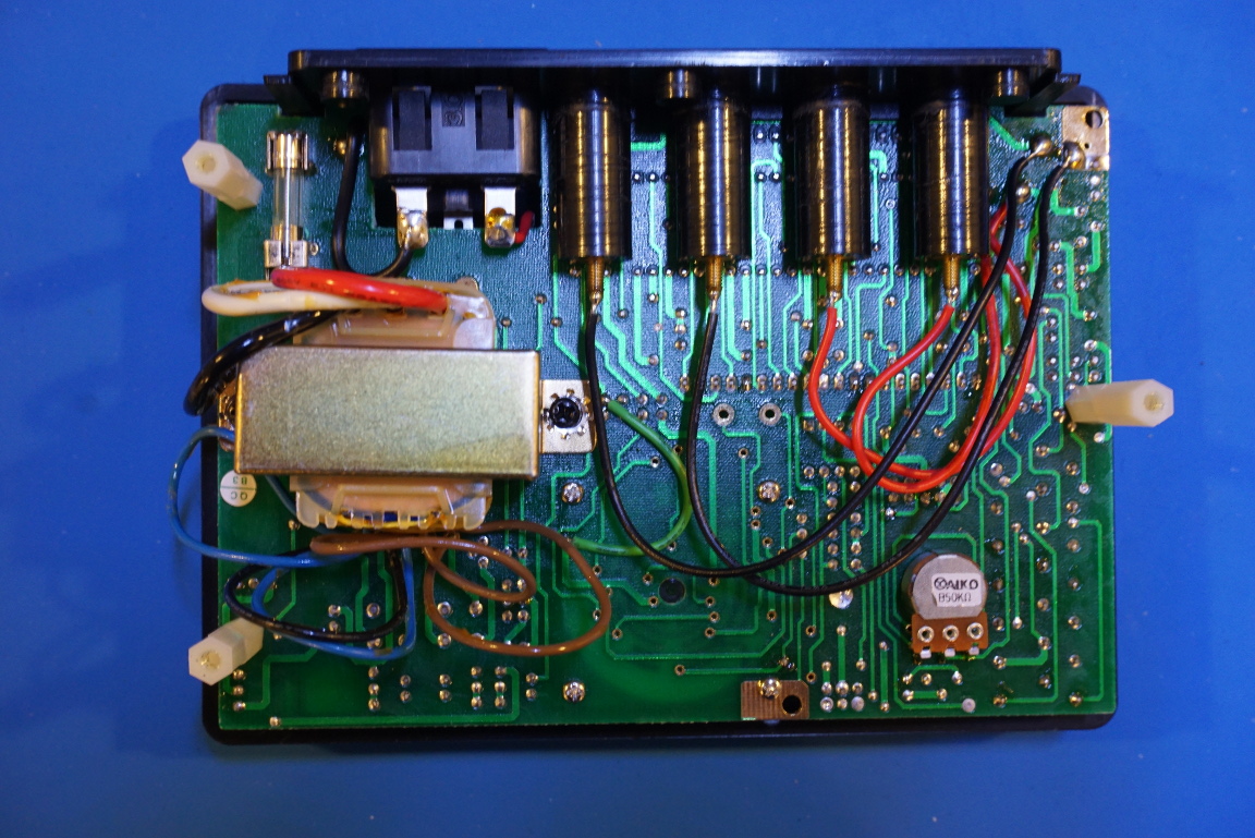
With the outer shockproof shell removed, we can see the circuit board inside. Besides the power transformer, there is not a whole lot going on on the reverse side of the PCB.
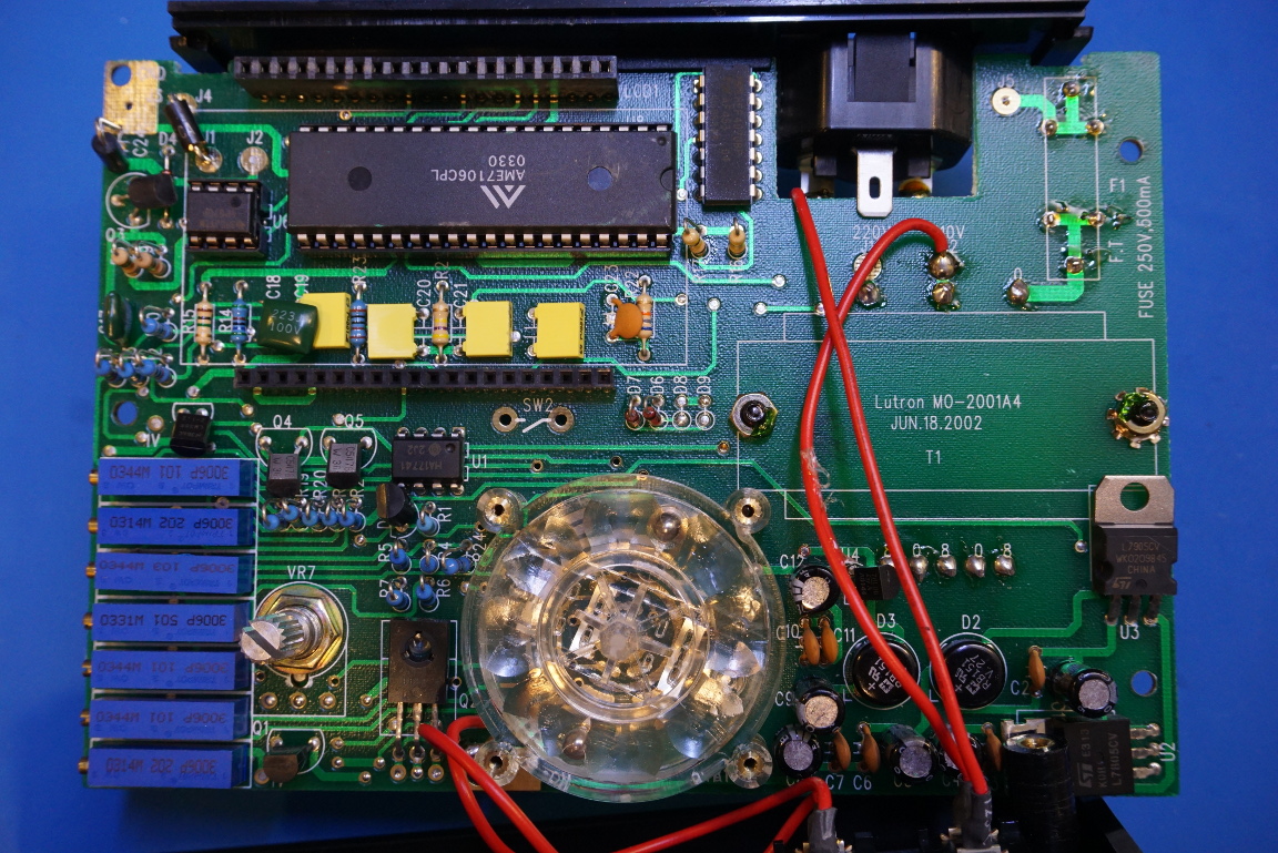
Here is the front side of the main PCB. I had to remove the two panel knobs in order to free it. From the date code on the PCB, you can see that this board was made back in 2002. Towards the bottom right you can see a couple of bridge rectifiers and two voltage regulators (7805 and 7905) which provides the ±5V supply the meter needs. The decision not to make this meter battery powered is likely due to the 100mA current requirement when measuring resistance under 200mΩ. But there is plenty of space inside this meter, you can easily fit a battery pack and a DC/DC converter circuit for the negative power.
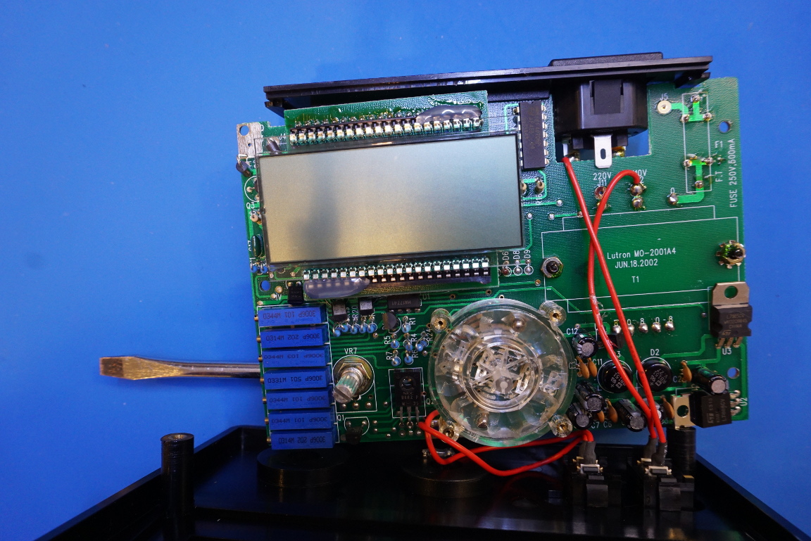
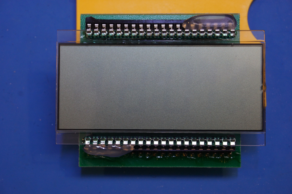
The LCD is mounted on an adapter board, which mates onto the mainboard using standard header connectors. Interestingly, the LCD board was made back in 1994 according to the date code (I forgot to snap a picture, but you can see it towards end of the linked video below), which was eight years before the main PCB was made.
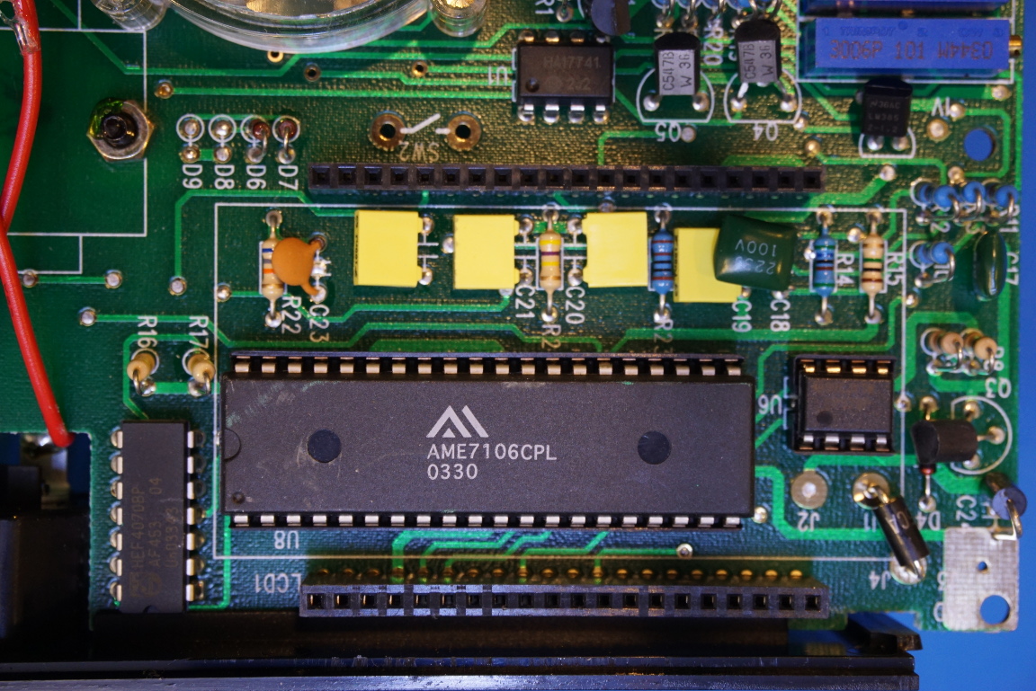
The main digital chip is an AME7106CPL 3½ digit A/D converter chip which is widely used in multimeters. In fact, this A/D converter and the 4070 quad XOR gate chip are the only digital chips in this meter. This is somewhat to be expected however, as all a milliohm meter needs is a precision current source and a precision A/D converter for the voltage measurement readout. You can easily build one yourself.
To the right of the A/D converter is a socketed precision Opamp OP07, I think this is probably part of the constant current circuitry. Towards the upper right corner, right under the precision trim pot there is a 2.5V LM385 voltage reference. Again, this would be for the constant current generation. The only remaining 8 pin IC is a uA741 variant general purpose OpAmp which is soldered on directly.
Again, here is a picture of the main circuit board with the LCD module removed. There are a lot of precision trim pots there for calibration purposes. Unfortunately, I could not find any calibration procedures online for this meter. It is probably a good idea to leave those pots along.
In the video below, I did some testing and followed by a teardown of this Extech milliohm meter.

