Recently I got hold of a dead APC SurgeArrest power strip that was about to be thrown out in my office. The power strip simply doesn’t provide power to any of its outlets regardless of the power switch position. Since there was no external fuse that I could find, I decided to take it apart and find out why and how it had failed.
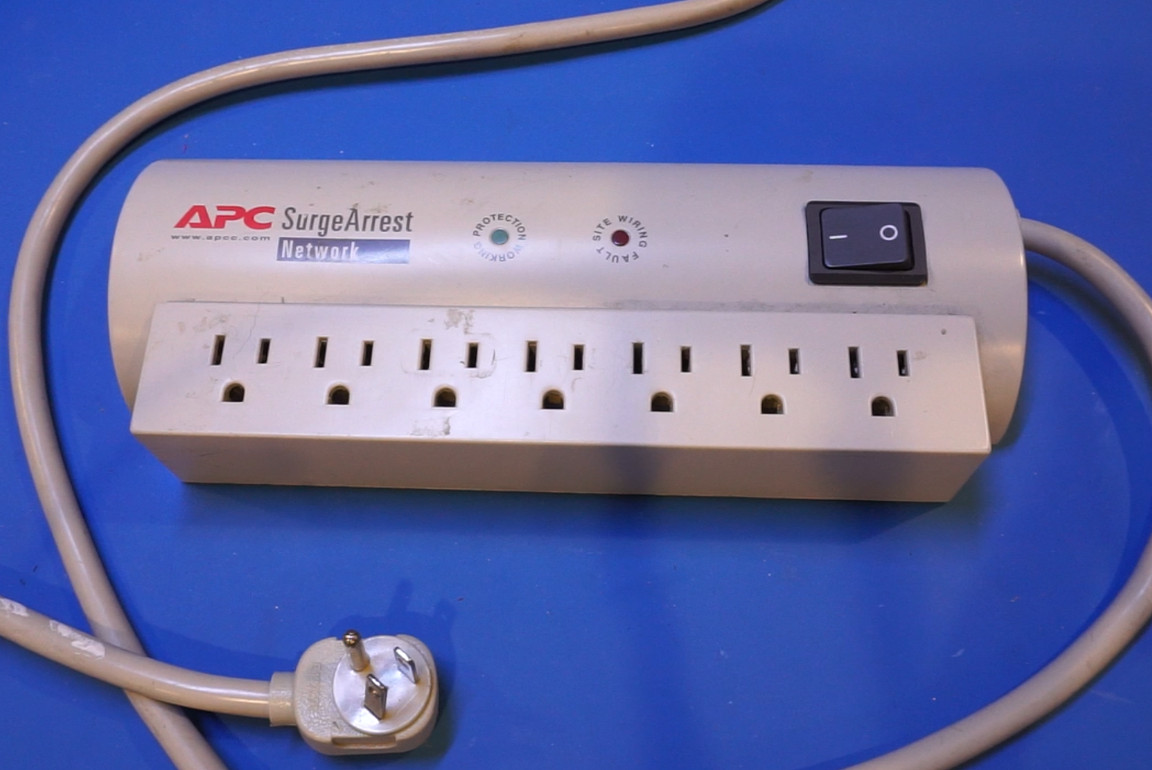
The model number of this particular APC surge protector is NET7. A quick search led me to this page on the US consumer product safety commission (CPSC)’s website. And it seemed that this NET7 series had been recalled back in 2013 for the cited fire hazard.

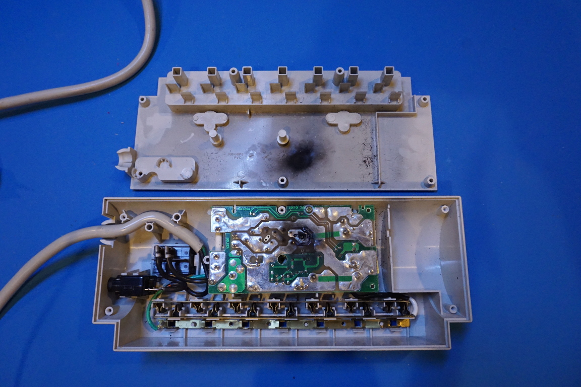
Upon opening up the power strip, it became evident that something had gone horribly wrong. It appeared that some components or the PCB had been burnt judging from the soot inside the cover.
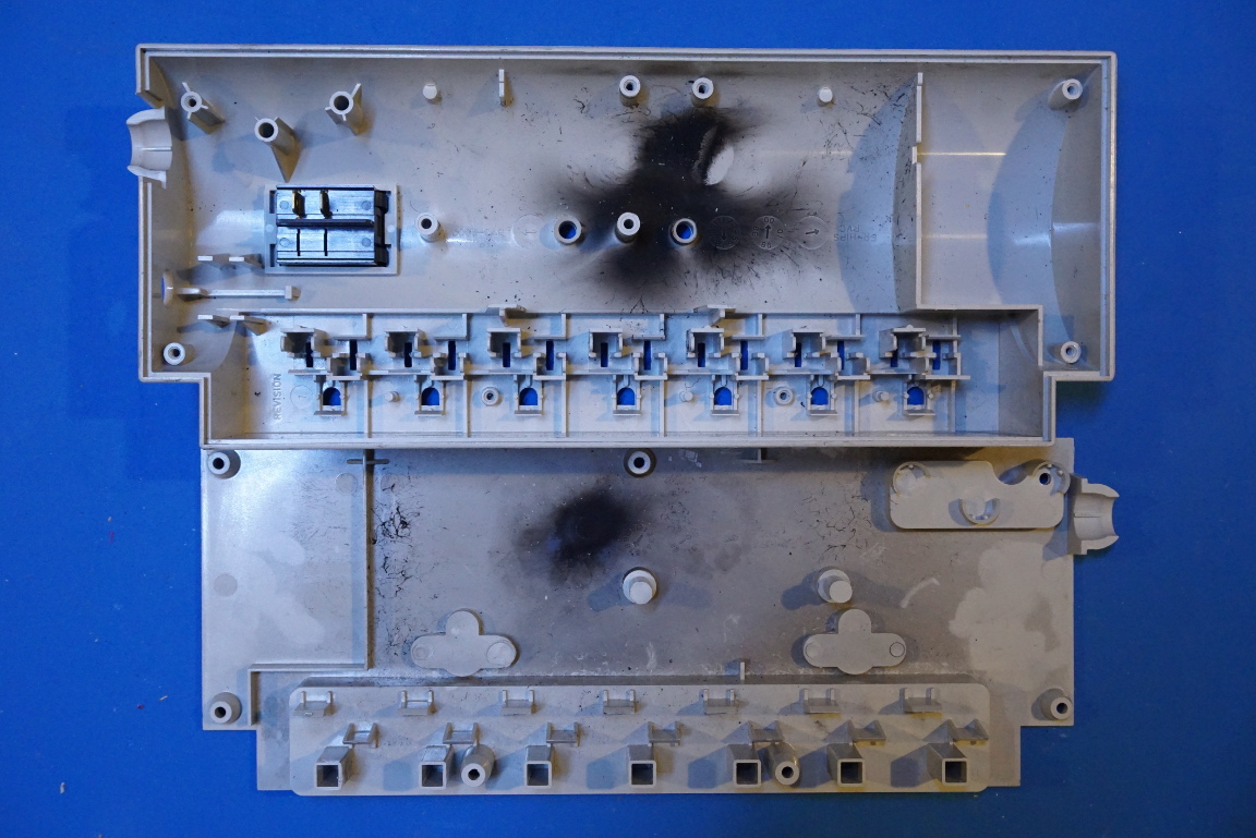
In the picture to the right, you can see similar soot deposit in the bottom half of the enclosure.
|
|
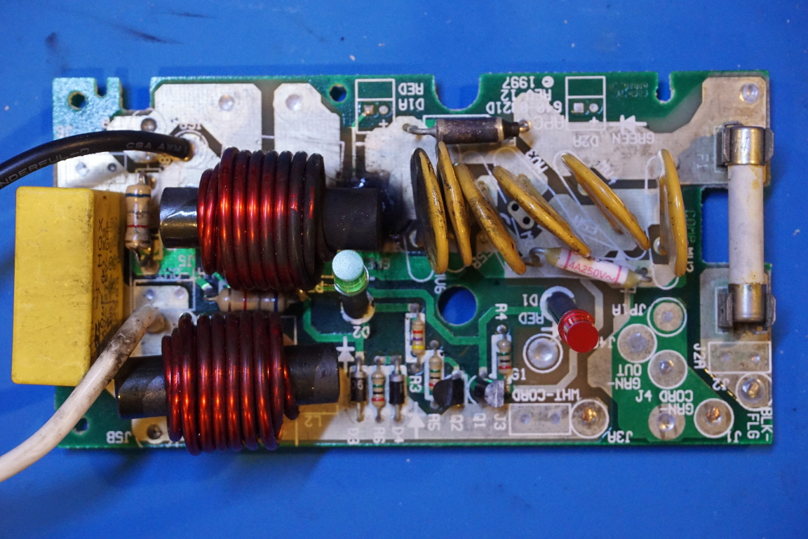
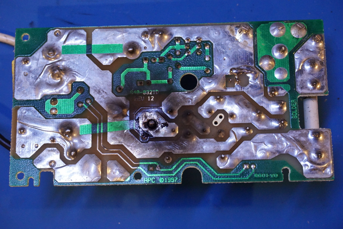
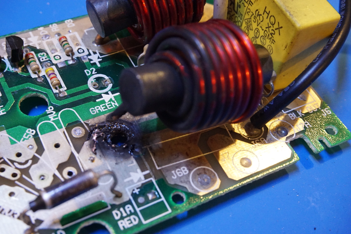
And here are a couple of pictures showing the closeup of the circuit board after it was removed from the enclosure. As you can see, it appeared that a high energy event — either the power strip was grossly overloaded or there was a short in the connected load — caused the solder joints in one of the coils to melt and presumably there was also some arcing over after the low conductivity path had been destroyed and caused the PCB to burn.
Luckily though, because the circuit path was interrupted after the solder joint was burnt, no further damage was done.
|
|
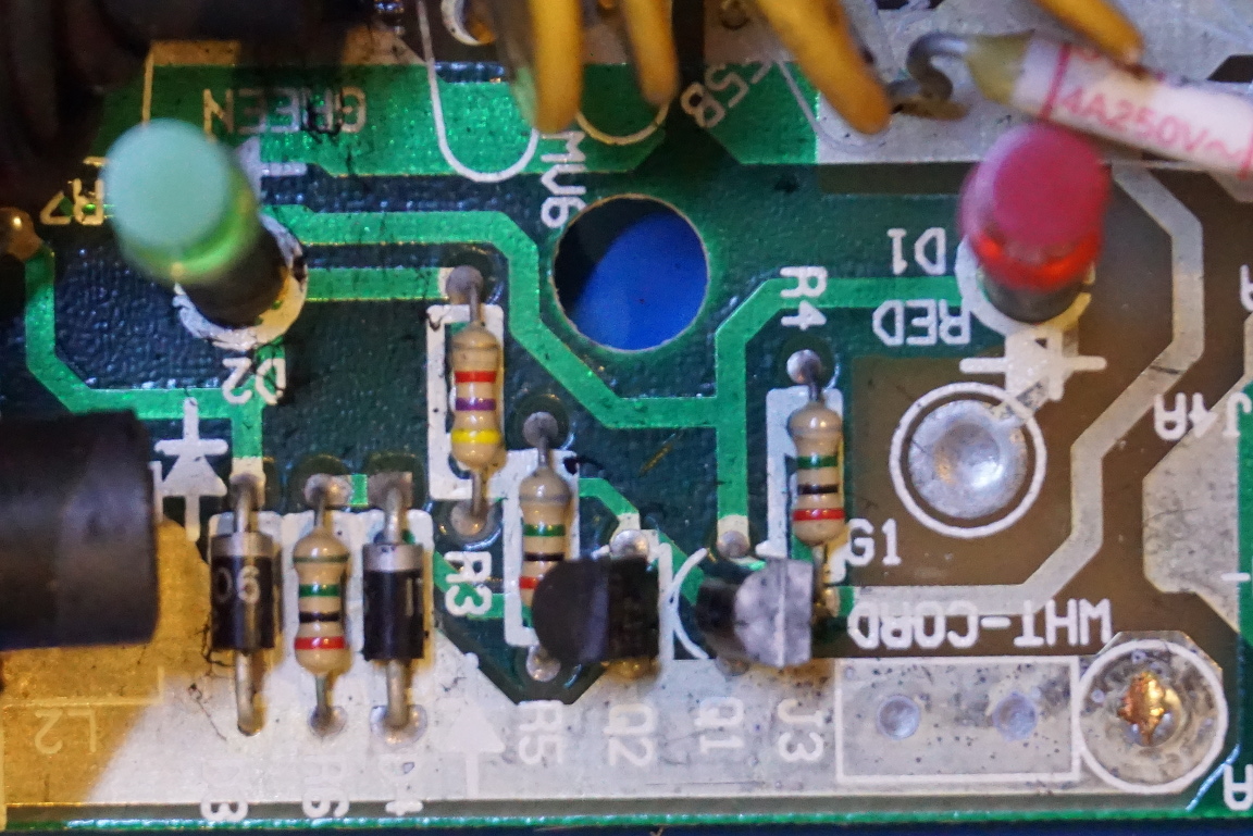
After I desoldered some of the components, you can see more clearly the extend of the damage. In the picture below you can also see the darkened resettable fuse along the current path. Interestingly enough though, the resettable fuse and the main 25A fuse remain intact. This should not have happened as the PCB trace should have been designed to allow the rated current flowing through without causing any damage. And the main fuse should have been the one that interrupted the circuit in the event of a sudden surge of load current.
Could this have been the reason why this NET7 series of surge protectors had been recalled?
Besides the standard MOV surge protection circuitry there is a portion of circuit for driving the two LED indicators. I did a quick reverse engineering discussed its principle of operation in the short video towards the end.
A PN2222A NPN transistor is used to drive the green power-on indicator LED. And a Darlington transistor MPSA13 is used here for wiring fault detection.
Here is a short video showing the teardown and failure mode analysis:

