I did a review on Topward’s 6603A linear power supply last time. In my opinion, Topward 6000 series power supplies are really well made and offer exceptional performance. One minor annoyance though, as I mentioned, is that the two cooling fans are constantly on. This makes the otherwise great piece of lab equipment rather noisy, even when the load is light.
My plan was to add a simple thermal controller that only switches on the fan when the temperature rises above a certain threshold. According to the service manual, the two 12V DC fans in the power supply are connected in series and powered by the 24V auxiliary power directly. So adding a temperature controller is a rather simple task.
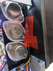
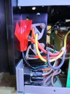
The following diagram illustrates the heat sink layout of this power supply. It is essentially consisted of two separate heat sinks, one for each channel. The power transistors are mounted on a vertical fin that is perpendicular to the main heat dissipation surface. Due to the design, the temperature gradient can be quite high from the place where the TO3’s are mounted to the edge of the heat sink fins. So it is necessary to place the sensors as close to the power transistors as possible. Also, because the two channels of the power supply can be operated indecently we will need two temperature sensors, one for each channel. This arrangement can be seen in the diagram below.
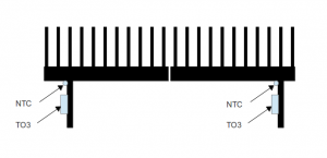
I could have designed a PWM controlled fan controller that automatically adjusts the fan speed depending on the heat sink temperature. But since for the majority of the time the power supply will be used well below its rated dissipation power, I actually prefer to only have to turn on the cooling fans when necessary and keep the on duration as short as possible. This way, the power supply can remain totally silent most of the time.
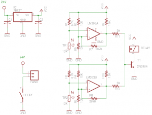
The circuit diagram below shows my simple design to accomplish this. A half LM393 dual comparator forms a Schmitt trigger which is used for each channel, and the control circuits are identical for both channels. The NTC thermistor I used is B57891M0103J000, which has a nominal resistance of 10K under room temperature (roughly 77 F) and 6.5K around 100 F. Using the resistor divider values shown in the circuit, the trip point (high threshold) is right around 100 F. The slight positive feedback introduced by R7 and R8 will give an approximately two degree window so the low transition temperature would be around 98 F. The output of the two comparators are then OR’d to drive the relay. Or course you don’t necessarily need to use a relay, you could just use a power transistor or MOSFET.
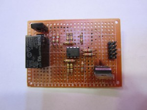
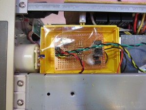
Here is a picture of the finished fan controller circuit board:
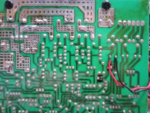
The relay can be inserted anywhere in the path of the fans connected in series. I chose to place the relay between the two fans so that I could use the exiting wiring. The only wiring change needed is the addition of the two wires that bring the 24V to the controller board as shown in the picture below (the original fan connections are marked using black marker).
There is plenty of room inside the Topward 6603A for me to place the controller board. I happen to have a case that snaps nicely between the transformer and the front panel.
Here are a couple of pictures showing the placement of the thermistors.
 |
 |
I am quite pleased with the result of this simple hack. Now my Topward 6603A is silent most of the time and the fans only come on briefly every so often when the power dissipation is high enough.

