Traveling-wave tube (TWT) is mainly used to amplify signals in the microwave frequency range. Unlike most vacuum tubes, which had largely given way to their more elegant semiconductor counterparts many decades ago, TWT is still being widely used today in many areas, especially in places where low noise and high output power is needed. I had always wanted to get my hands on one so when I saw an old HP 493A microwave amplifier for sale for peanuts, I simply could not resist snatching it.
I am not sure exactly when HP 493A was first produced, but from the date of the manual and a 1962 HP Journal article , it seems likely that it was first introduced in the early 60’s. Like many test instruments of the era, 493A was made using vacuum tubes and germanium transistors. Although according to the date codes on various components in my 493A, my particular unit seemed to have been manufactured in 1983. The more-than-two-decades product life cycle is certainly impressive as one can hardly imagine any products made nowadays run a course this long.
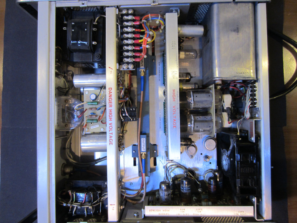
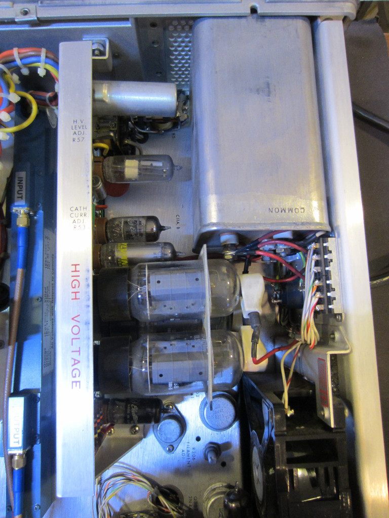
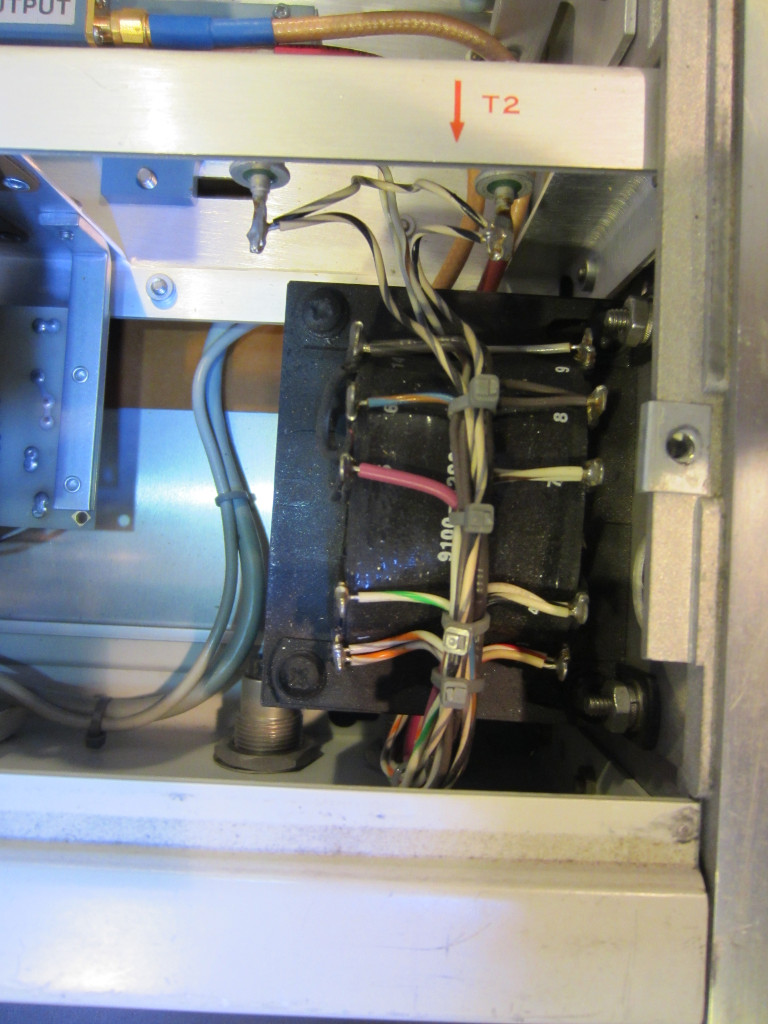
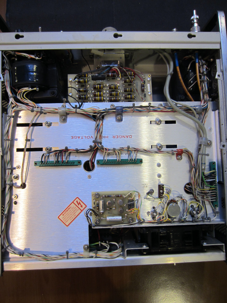
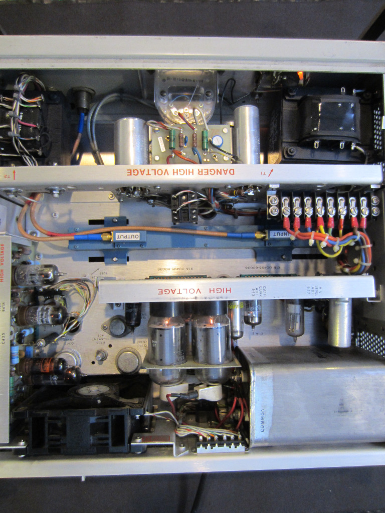
Before powering it on, I took a look inside just to make sure nothing is horribly amiss. The first picture to the left below shows what you see when the top cover is first removed. There are two power transformers, the one towards the bottom (T2) is the low voltage transformer, which provides power to the tube filaments and the modulator. The high voltage power transformer (T1) is at the top, it supplies the high voltage required by the TWT after the output voltage is rectified and regulated. Depending on the TWT used, the output voltage could be anywhere from just under 2000V to almost 3000V.
Here are some of my advice when dealing with high-voltage circuits, as it can be very dangerous if you are not careful.
- First and foremost, heed those warnings! There are lethal voltages everywhere when the circuit is energized, even the output of the low voltage transformer is more than 200V. You will really need to be familiarized with the circuit layout before attempting any live trouble shooting procedures.
- Second, try use only one hand at a time when probing the live circuit so you don’t accidentally put a high potential across your torso (which would be deadly).
- And if you could, use an isolation transformer to power the equipment.
- Last but not least, always use a high voltage probe to confirm the voltage you are testing before proceeding with a multimeter. Most multimeters cannot handle voltages higher than 1000V, you could easily damage your multimeter and injure yourself if you accidentally touched the wrong voltage with your standard probes.
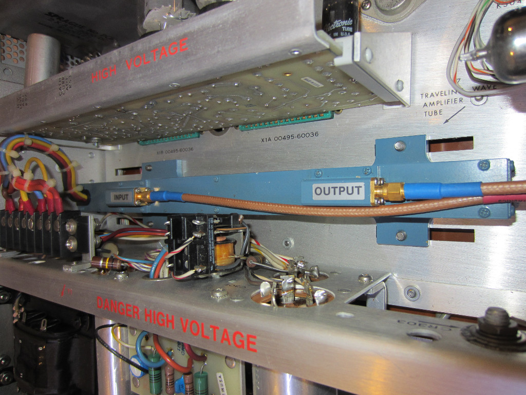
In the picture to the right you can see the blue TWT in the middle. Very briefly, here is how a TWT works: RF signal enters the tube towards the cathode on the left. It travels along a helix towards the anode (hence the name traveling-wave tube). Electrons emitted from the cathode are focused via external magnetic field and accelerated towards the anode. In the mean time, Electron bunching occurs when field induced by the RF signal interacts with the electron beam. So as the RF signal is coupled out from near the anode, the signal is magnified due to the electron bunching effect.
|
|
So the basic supporting circuitry for a TWT to be operational is pretty simple. All you need is the filament voltage to heat out the cathode, a high voltage supply for the helix coil and anode and a grid voltage to control the density of the electron beam. Of course, the power supply voltages need to be precisely controlled in order to prolong the life of the tube and obtain optimal performance.
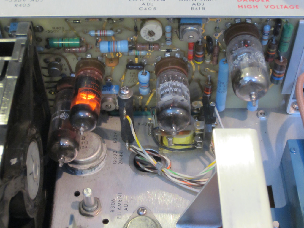
Here are pictures showing the negative voltage (-350V) board and the HV regulator circuitry (on the right). The two beefy vacuum tubes are the high power 8068 pentodes, which regulate the high voltages required by the TWT helix and anode.
|
|
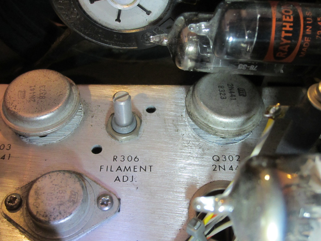
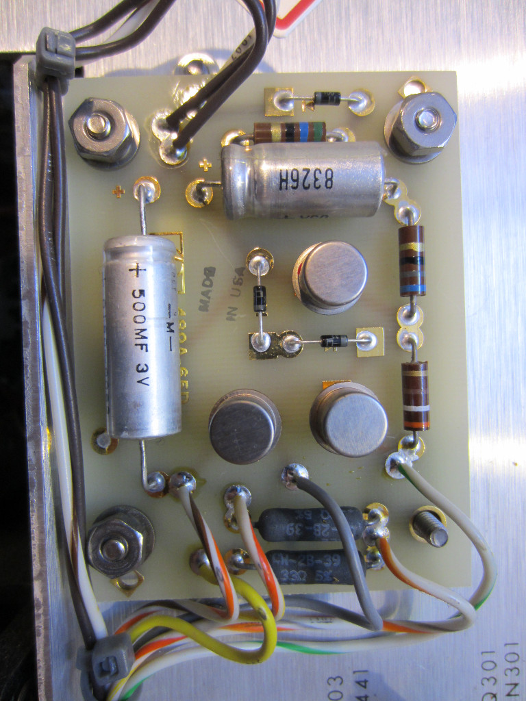
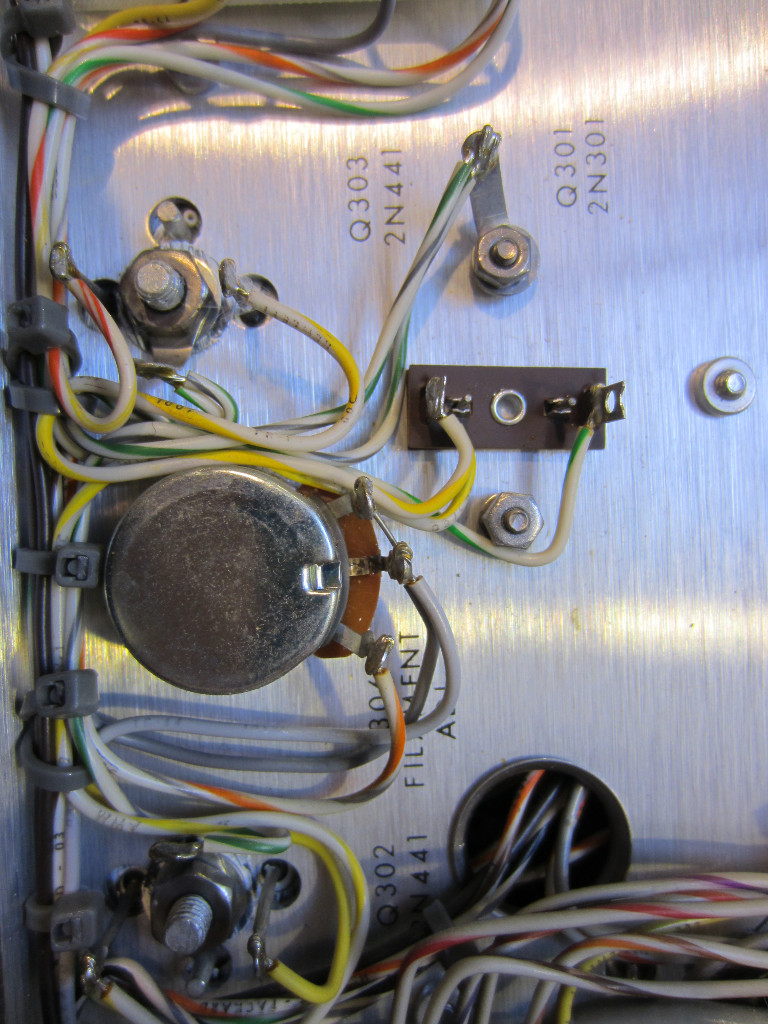
The transistors used in 493A are all germanium ones. They form the filament regulator for the TWT. From the date codes we can tell that the transistors were manufactured in 1983. Most other components have the 83 date codes as well which suggest that the unit was probably made back then.
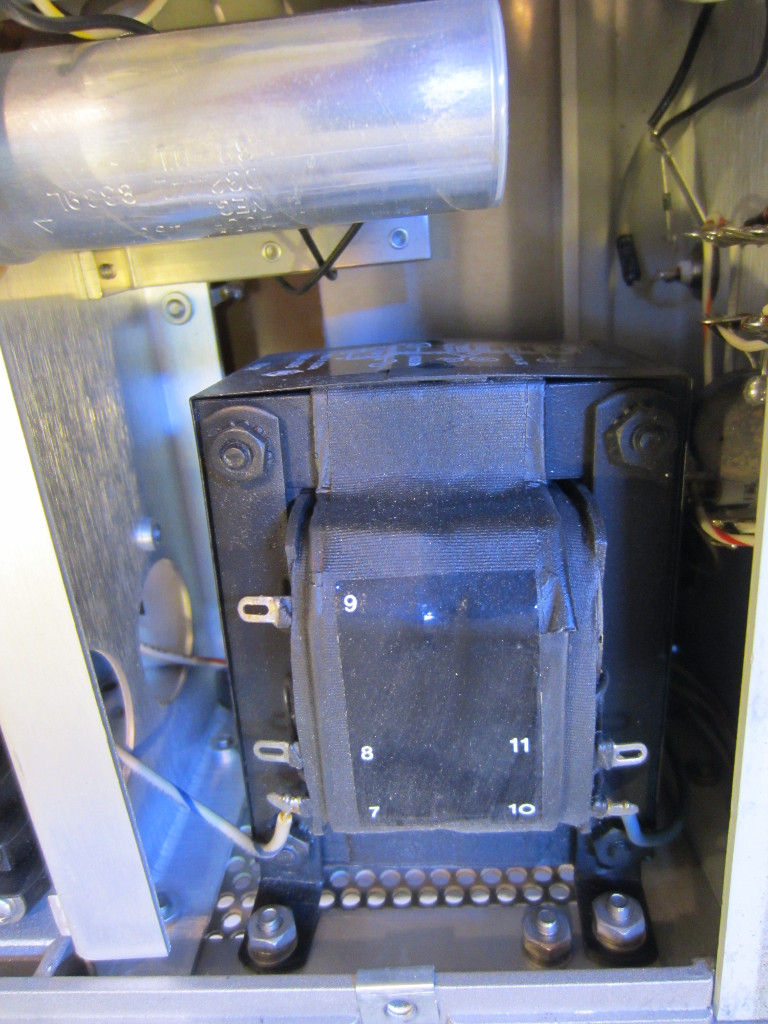
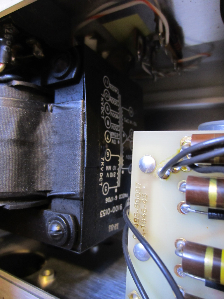
The picture on the left below shows the high voltage transformer. As mentioned earlier, the secondary outputs thousands of volts. The connectors are exposed and there is nothing (except for the warnings) guarding against being touched accidentally. This design probably would not have passed today’s much stricter safety standard but was quite acceptable in the early days.
On the right is another picture of the low voltage transformer (one winding is still more than 200V).
|
|
Here is a picture of the high voltage transformer from another angle, you can clearly see the voltage ratings on the side.
This picture on the left below shows the cathode current measuring portion of the circuit. The meter on the front panel measures the voltage drop across a 1K resistor in the cathode current path.
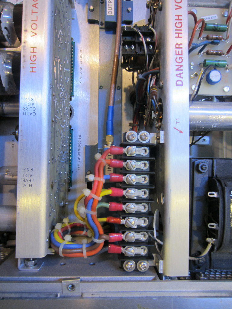
On the right side is the connector block for the TWT. Measuring the voltages across these connectors need to be extremely careful as mentioned earlier. The filament connectors are directly adjacent to the HV connectors so you could easily damage your multimeter and injure yourself if you probe the wrong connector when the TWT is powered.
|
|
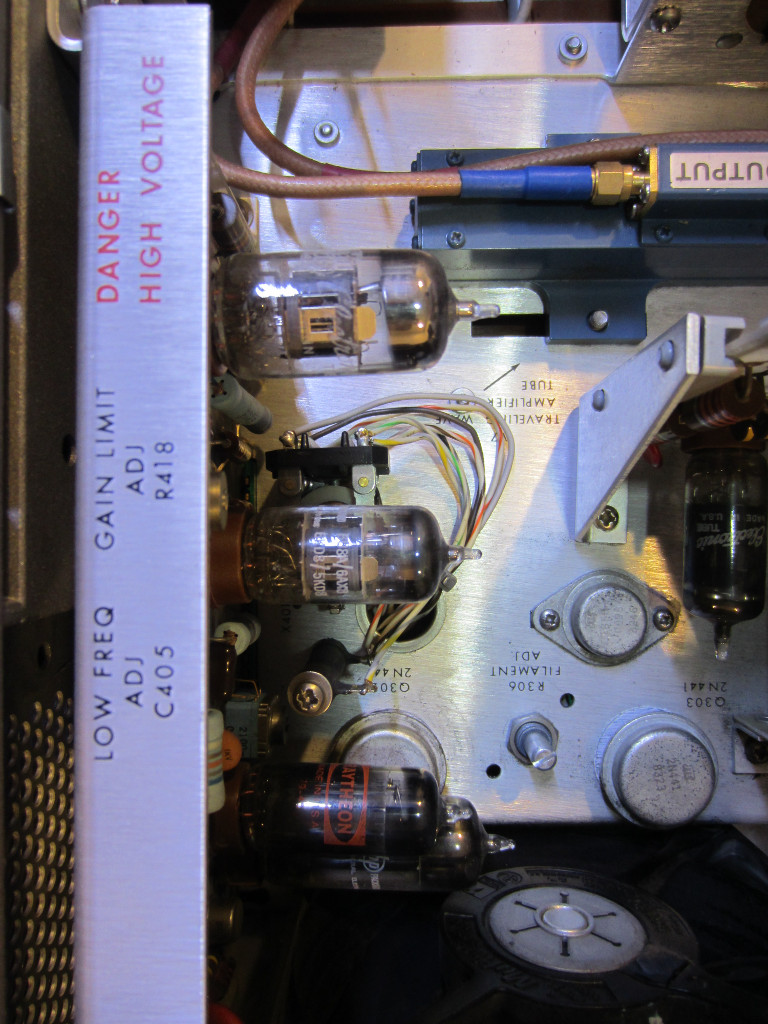
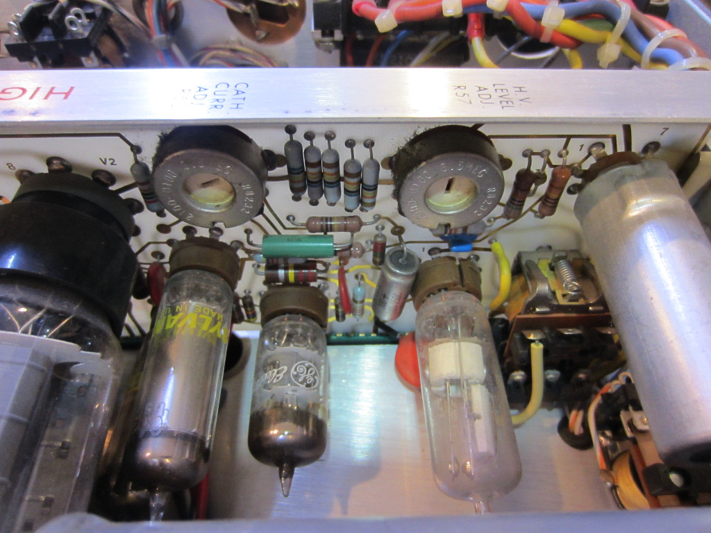
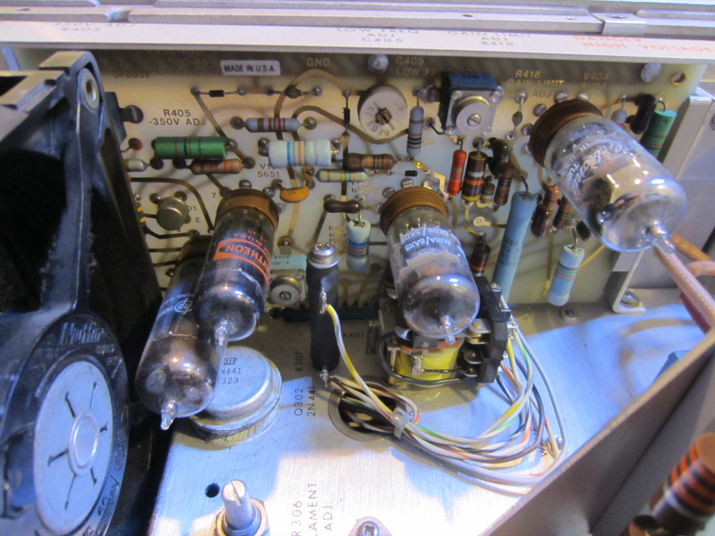
There are only a few potentiometers to adjust when tuning the TWT. The ones in the picture on the left adjust the grid voltage of the tube which in turn controls the gain, and also the frequency responses of the modulator. The ones on the right are responsible for the cathode current, and anode voltage.
|
|
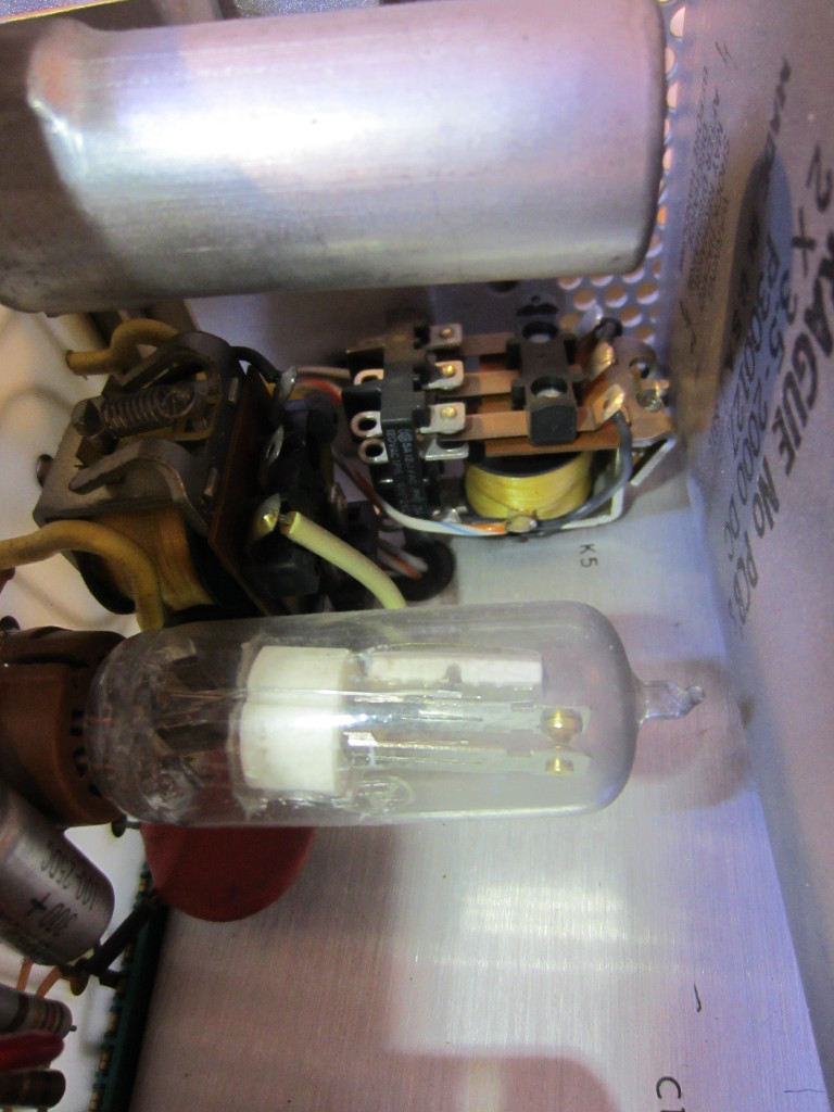
Here is a close-up picture of the vacuum tube time delay relay and the over-current protection relay for the TWT. The time delay relay controls the sequence of power applied to the TWT and only allows the HV to be applied after the cathode has been heated for a sufficient amount of time. The over-current protection relay will cut off the high voltage supply when it detects excessive helix current to protect the TWT from being permanently damaged by overloading.
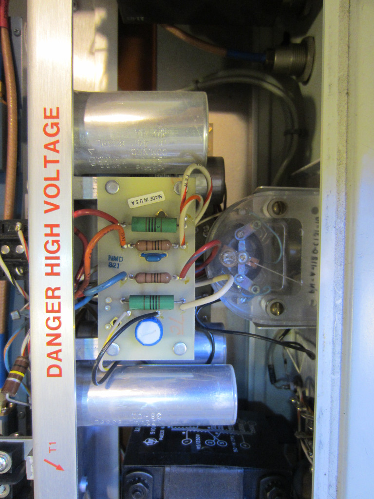
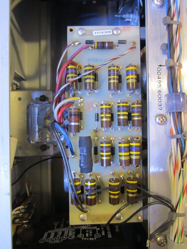
Here are a few pictures showing the underside of the HP 493A with the bottom panel removed. The picture on the right below shows the voltage doubler for the HV supply. Diodes are wired in series to increase the breakdown voltage.
|
|
The TWT filament voltage adjustment potentiometer can be seen in the picture below (right). By default, the TWT filament was set to operate slightly under voltage (6.2V) to increase the life of the cathode.
|
|
Here is a picture showing the unit powered on. You can clearly see the glow coming from the filaments.
I just can’t get enough of how beautiful the voltage regulator tube looks!
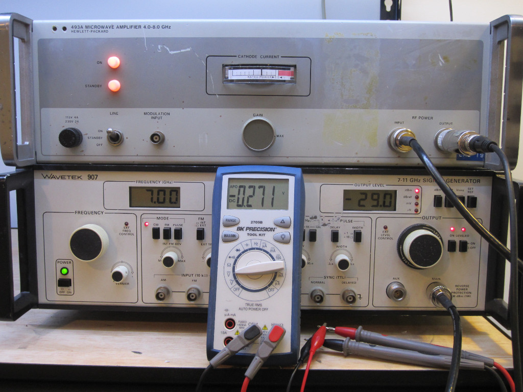
This HP 493A operates between 4 GHz and 8 GHz, and it did require some tuning to get back to its working order. When initially powered on, the cathode current was extremely small (only around 1/8 of the scale) and thus magnification was low. I then followed the service manual and adjusted the anode voltage and various voltages settings and was able to get it back in decent working order. The picture below shows the output power from the 493A. The input signal was generated using the my Wavetek 907 I fixed earlier. With the input set at -29 dBm the output from the HP 420A crystal detector is slightly above 3 dBm (roughly 0.1v/mW), so the overall power amplification is just above 30 dB. This is on the lower side of the spec’d performance, but given the age of the equipment I am quite happy with the results.