In electronics, guarding is a technique typically used to prevent or minimize current leakage from a high impedance source. This method is widely used in many low level measurements especially in low current and high resistance measurements.
By definition (see Low Level Measurements Handbook 7th Edition), a guard is a low impedance point in the circuit that is at nearly the same potential as the high impedance input terminal. Intuitively, Ohm’s law suggests that when a high impedance source is at nearly the same voltage potential as the guard ring, the current flow between the high impedance source and the guard is close to zero.
When doing low current measurement using a picoammeter or electrometer, the guard is typically the LO input terminal of the ammeter. Because both electrometer and picoammeter utilize the feedback ammeter technique, the burden voltage is extremely low (usually in several hundred μV range) and the leakage current between the HI and LO terminal is thus negligible. Since the LO terminal is essentially floating, any leakage current between LO and the ground terminals will flow through LO and thus does not affect the measured current.
When doing high resistance measurement or measuring voltage from a high impedance source, it is necessary to eliminate the effect of the cable resistance. The cable resistance is in parallel with the unknown resistance to be measured which could affect the result accuracy significantly if the desired measurement range is comparable to the cable resistance (usually tens of GΩ). To do this kind of measurements properly, the output from the voltage source is typically guarded alone the cable that is carrying the voltage signal. Since the guard voltage is at near the voltage source potential, there is almost no current flowing from the voltage source into the guard and thus the current leakage from the guard does not affect the measurement (this current is sourced from or sinked into the guard amplifier).
Guarding is usually implemented using a voltage follower. In this configuration, the voltage difference between the positive and the inverse inputs of the Opamp is very small and the Opamp output voltage is held at almost the same potential as the positive input.
The following SPICE model illustrates how guarding works. In this model values are somewhat exaggerated, but the operating principle remains the same. Here R1 represents the resistance between the coaxial inner conductor and the outer shield and R2 represents the resistance between the outer shield and the ground (or if a triaxial cable is used, R1 would be the resistance between the inner conductor and the inner sheild and R2 would be the resistance between the inner shield and the outer shield).
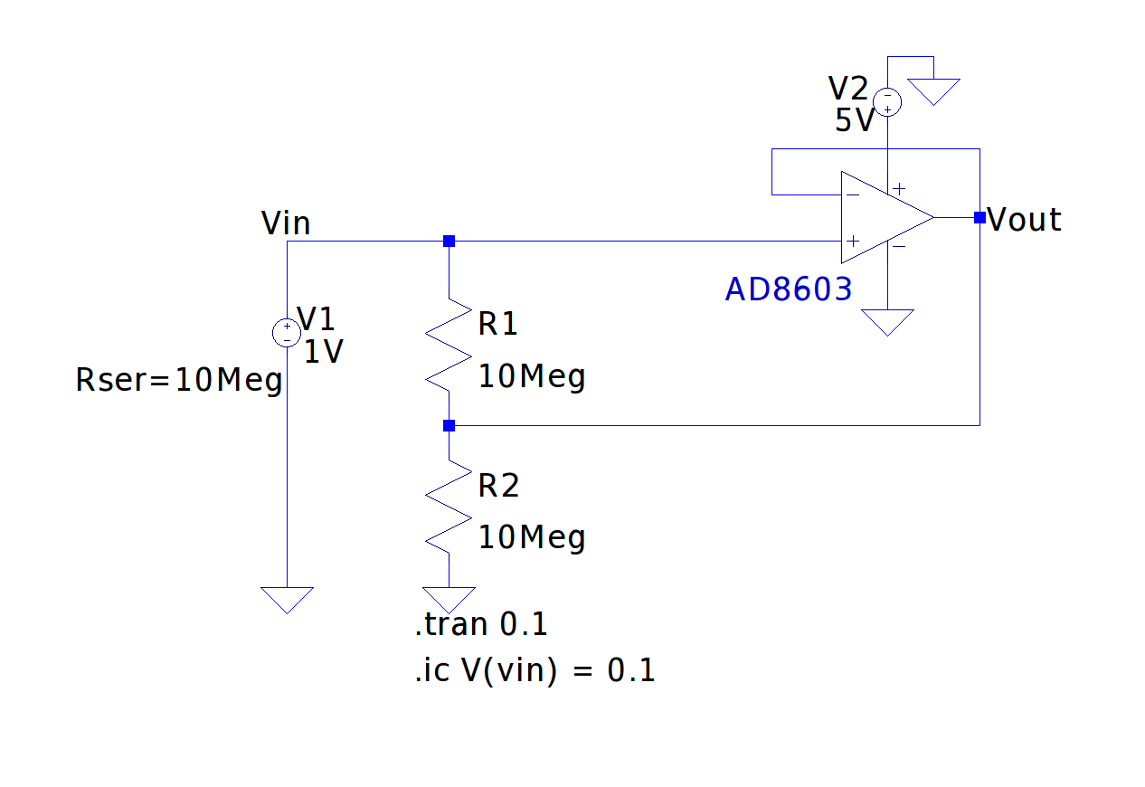
The voltage source we used here has an output impedance of 10 MΩ, which is comparable to the leakage resistance. Thus if the output voltage is measured directly, the measured value would be lower than the actual source voltage due to the current leaking through R1 and R2. If however, we add in the voltage follower and use its output to drive the shield (junction of R1 and R2), the voltage across R1 would be roughly zero and thus the source voltage measured at the positive input of the Opamp would not be affected by the cable leakage resistance R1.
Of course in this example, the loading effect of the voltmeter must also be taken into consideration due to the high impedance nature of the source. Typically we will need to use an electrometer for this kind of task.
Guarding also improves the measurement settling time. Any capacitance between the center conductor and the guard can be ignored as they voltage across this capacitor is negligible. Thus no significant charging/discharging would occur.
You can see a couple of related experiments in the video below:
|
View on YouTube in a new window |

