In this blog post, I compared the rise time of four oscilloscope probes of various bandwidths using an avalanche pulse generator and a Tektronix 2465 300 MHz oscilloscope. The bandwidth of an oscilloscope probe is typically characterized using a network analyzer. But using a sub-nanosecond rise time pulse generator and a reasonably high bandwidth scope, we can infer the approximate bandwidth of the probe under test using the following equation:
\[BW=\frac{0.35}{T_r}\]
The above equation assumes that the oscilloscope has infinite bandwidth and the measured rise time is caused by probe’s bandwidth limitation only. This equation works the best when the bandwidth of the probe is significantly less than that of the of the oscilloscope. In practice though, the measured rise time is affected by the signal’s rise time, the scope’s rise time and the probe’s rise time and is characterized by the equation below.
\[T_r = \sqrt{T_{signal}^2 + T_{sys}^2}\]
For our exercise, we will keep it simple by ignoring the rise time of the scope and the signal. Of course, by doing this we will introduce significant error in our measurement results. But we should still be able to see the relative performances among different probes.
For comparison purposes, I used four probes:
- Cal Test CT3288RA (500 MHz)
- Tek P6131 (300 MHz)
- Rigol RP2200 (150 MHz)
- Generic TP6100 (100 MHz)
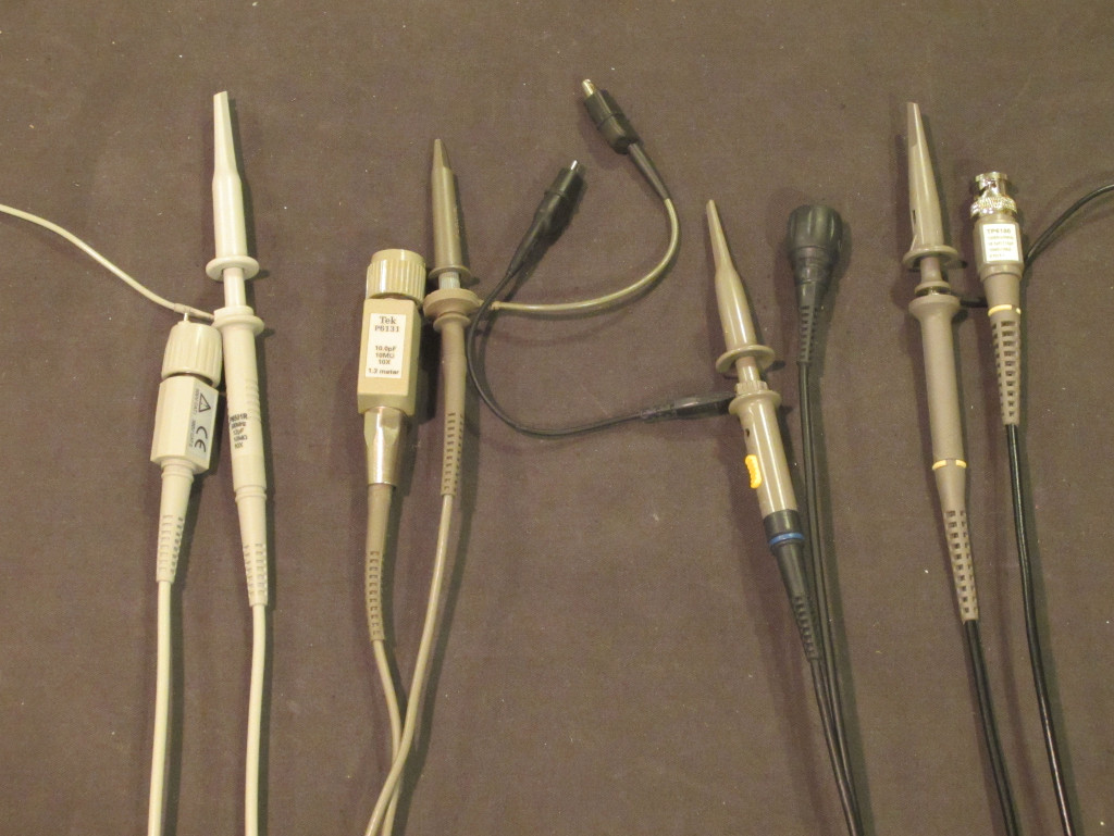
Here is a picture of the probes used in this test (from left to right: CT3288RA, P6131, RP2200 and TP6100):
The avalanche pulse generator used here is the one I built a couple of years ago. Before conducting the test, each probe was properly compensated using the probe calibration signal from the oscilloscope. All tests were done using channel one’s 50 Ω DC coupled input.
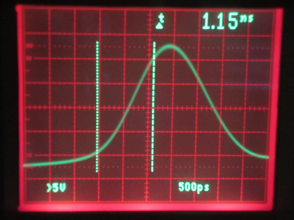
The picture below shows the baseline rise time of the scope when the pulse generator is connected to channel one directly. The measured rise time is 1.15 ns which corresponds to a scope bandwidth of 304 MHz.
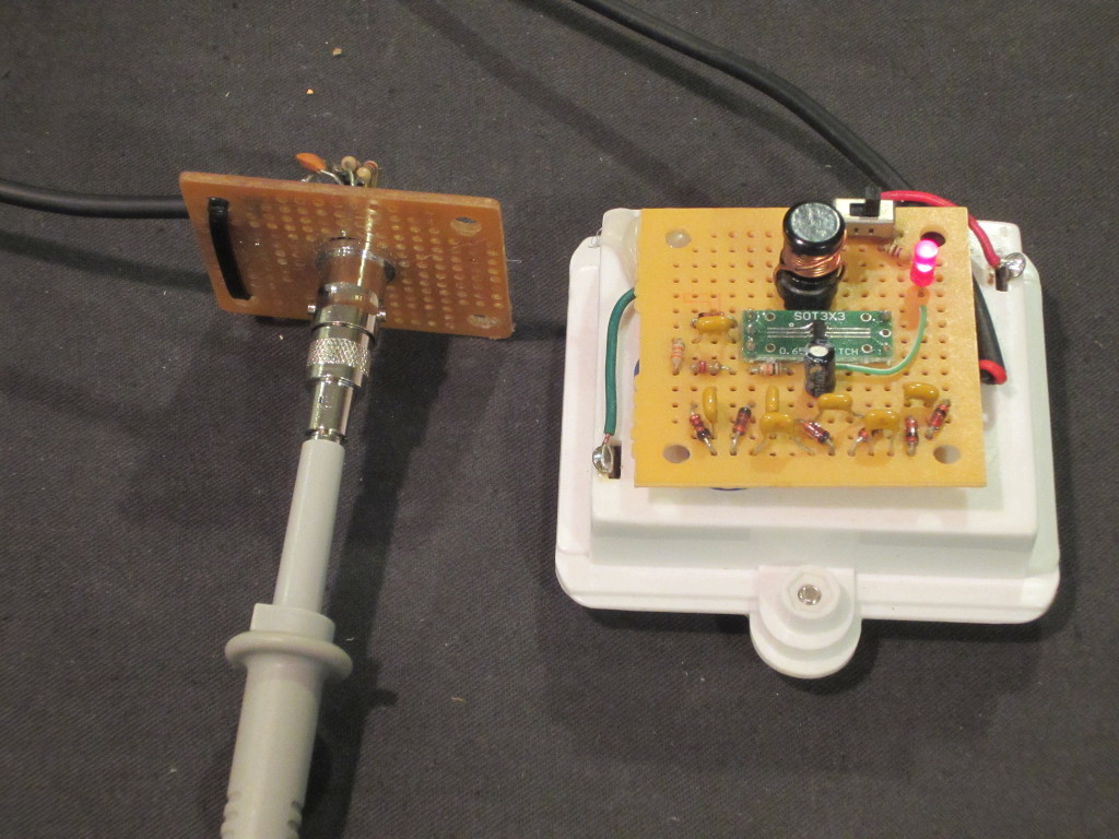
In order to minimize stray capacitance introduced by the probe tip and ground clip, a probe to BNC adapter is used (except for P6131 as I don’t have an adapter for that probe. So a ground spring clip was used in that case). The picture below shows my test setup.
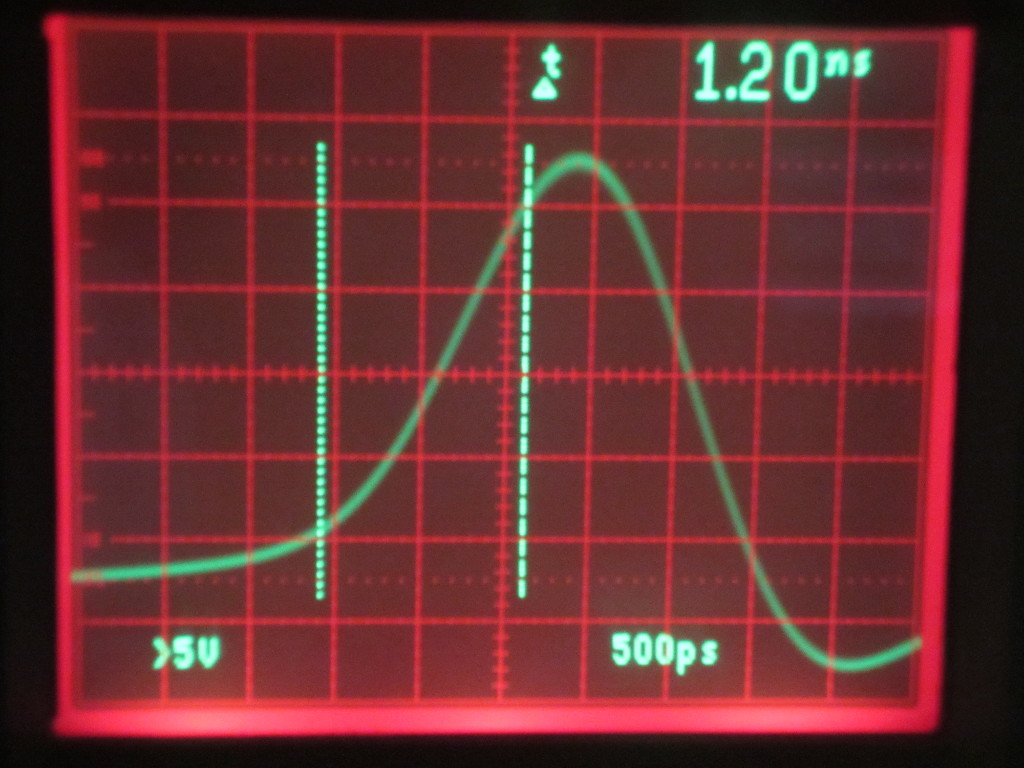
Because of the scope bandwidth limitation, we should see pulse rise time slightly less than that of the oscilloscope when using probes with a higher bandwidth. The screen capture below shows the pulse when measured using the 500 MHz probe. For a 1.2 ns rise time, the measured bandwidth is at roughly 292 MHz.
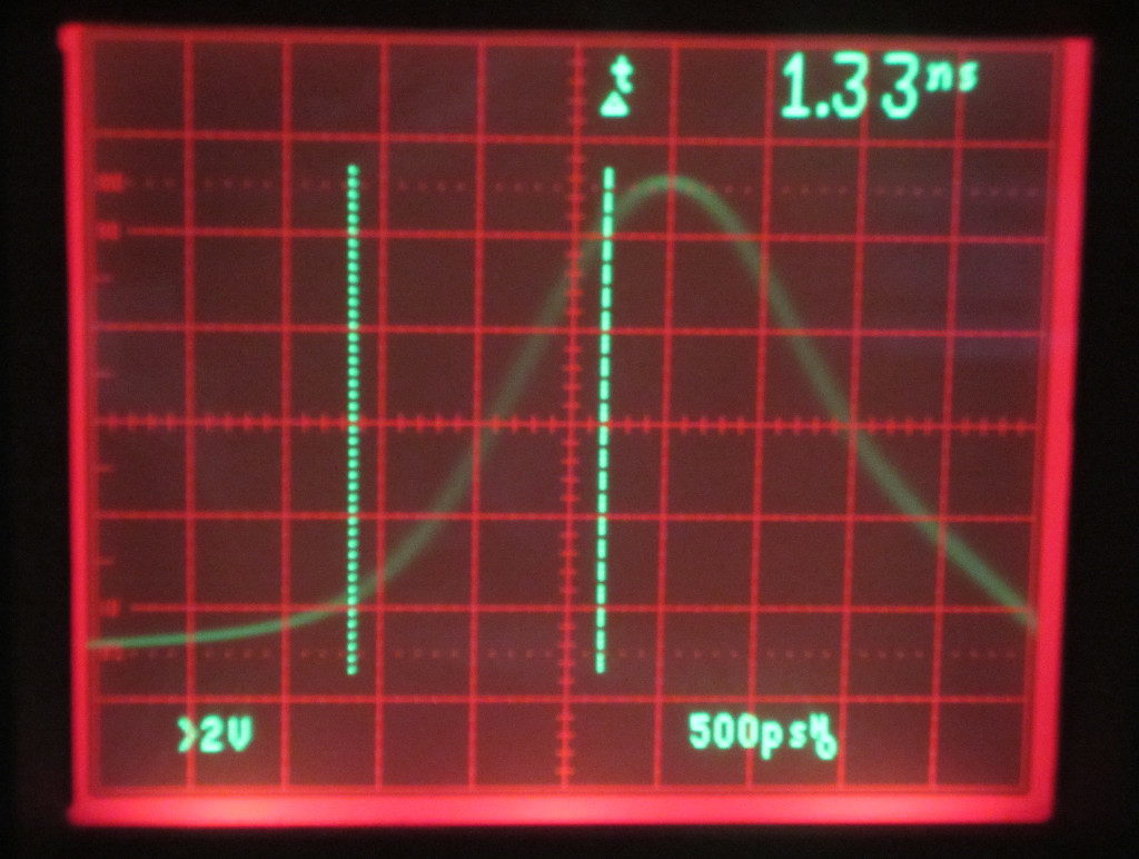
For the Tek P6131 probe (rated 300 MHz), the measured rise time is 1.33 ns which translates into a bandwidth of 263 MHz. As mentioned earlier, I used a ground spring clip for this measurement. So the actual rise time might have been slightly lower than what I measured if I used the same BNC adapter.
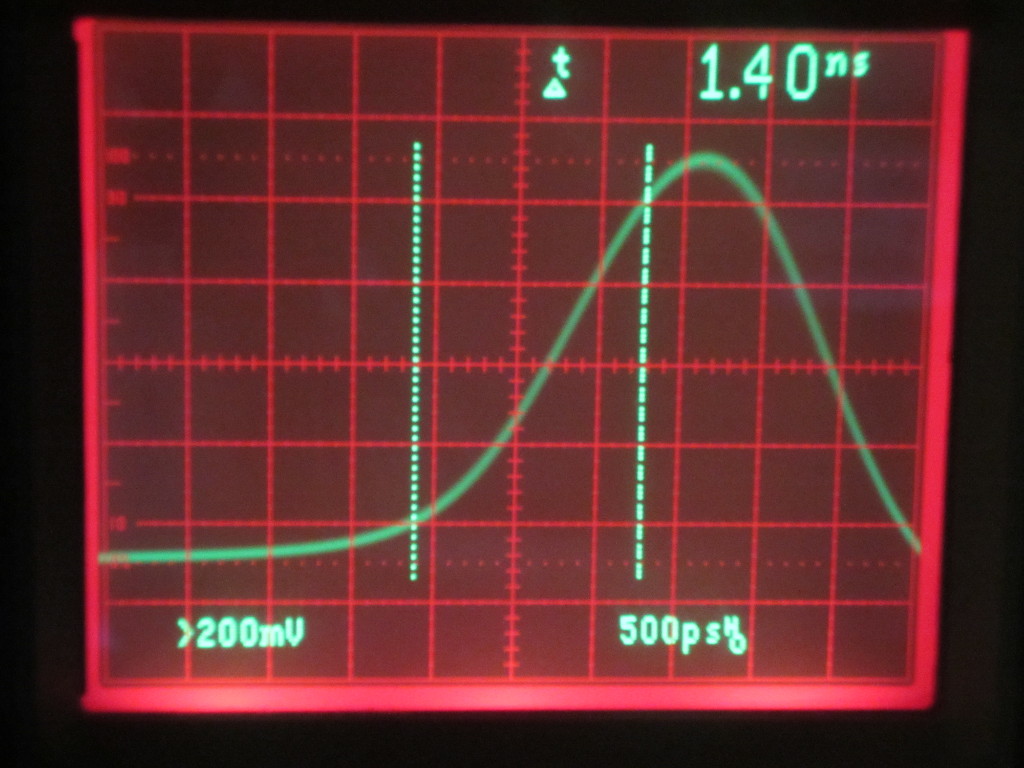
The Rigol RP2200 probe is the default probe for the DS1052E oscilloscope. It is rated at 150 MHz. In the oscilloscope capture below, you can see that the measured rise time is 1.4 ns which corresponds to a calculated probe bandwidth of 250 MHz.
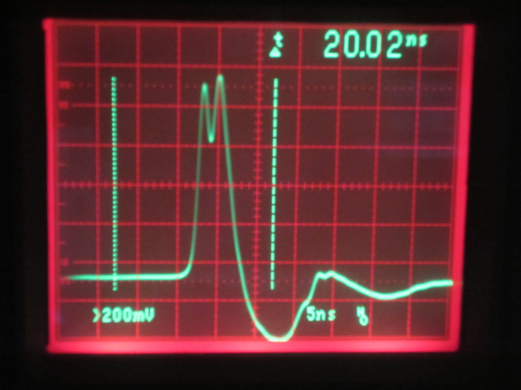
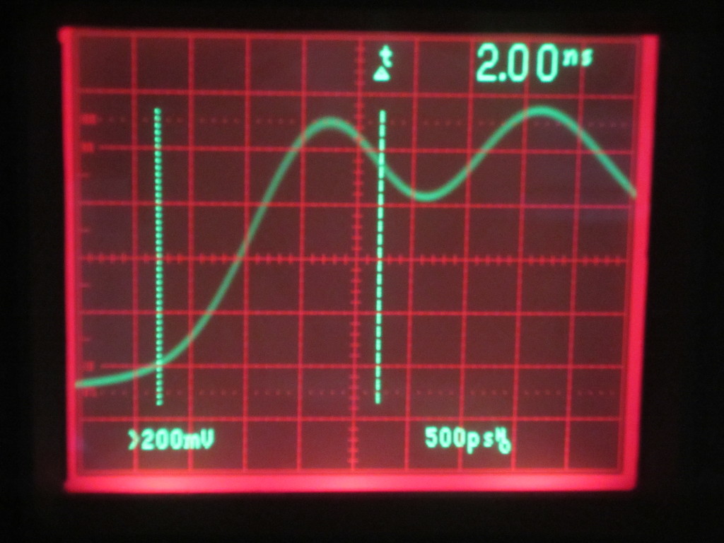
Finally, let’s take a look at a generic TP6100 100 MHz probe. These probes are sold on eBay for as low as $10 a pair. As you can see from the pictures below, the measured pulse is severely distorted. The measured waveform has two peaks (possibly due to reflection) and it is impossible to infer the rise time due to the irregularity of the waveform. So clearly, while this probe may be able to measure signals at 100 MHz the waveform fidelity will be significantly compromised.
|
|
The conclusion here is that when choosing a probe its bandwidth should be higher (or at least the same) than the oscilloscope you are using in order to obtain accurate results near the oscilloscope bandwidth limit. And don’t skimp on probes as cheap probes can distort signals at higher frequencies and making the measurement results invalid.
Of course, cheap probes do have their places. If you are mainly working with digital signals, the actual shapes of the measured signals may not matter much especially at lower frequencies.

