After taking the SMART UF-55 projector apart, I decided to take a look at the salvaged circuit boards to see whether I could re-use them to power the projector discharge lamp. Most of the modern projectors utilizes some kind of “smart” ballast circuits so that the main board could communicate with the ballast to determine the correct drive level given the required luminous level and monitor the operating temperature.
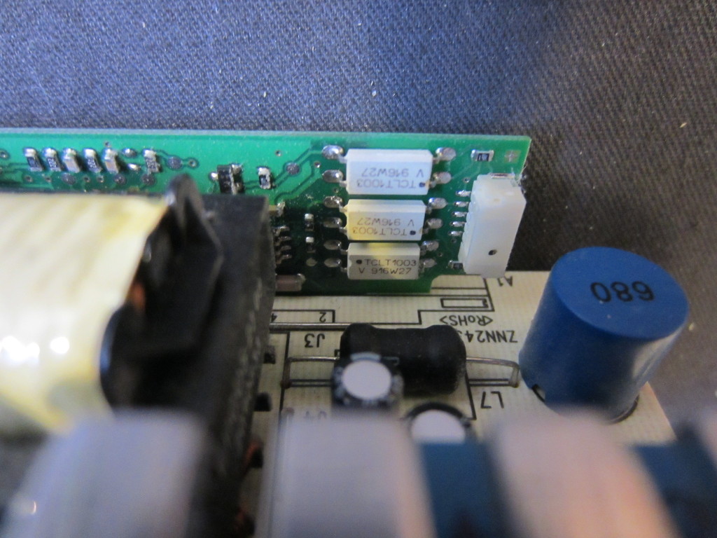
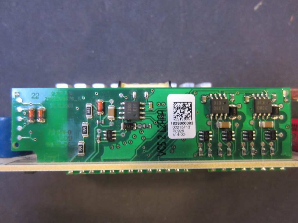
So turning on the discharge lamp without the projector circuitry requires a bit more than just applying power. The ballast board inside the UF-55 projector uses OSRAM‘s P-VIP PC-UART interface board, which communicates with the main projector board to regulate the power going into the lamp.
|
|
According to the application note, pin 4 (SCI/Sync) and pin 5 (DIM/RxD) are responsible for receiving commands from the host (e.g. the main board). The communication protocol is detailed in this document.
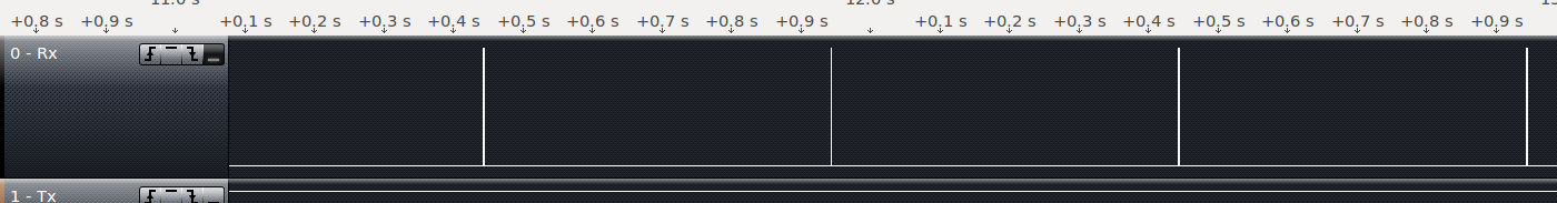
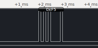
The UART protocol used by the P-VIP lamp interface board is 9600/8-E-1 (Baud rate 9600, 1 start bit, 8 data bit, 1 stop bit and even parity bit). Using a logic analyzer, I captured some data on the RxD pin (pin 5) during the normal operation of the lamp (with everything connected except for the DLP assembly and the auxiliary board). Once the lamp has been turned on, a status check command (0xF5) is sent at a rate of roughly twice per second (note that the UART waveform is inverted because the LEDs in the optocoupler are configured as common anode).
Here are the commands sent to the OSRAM P-VIP lamp driver during the initial power up. The commands were issued at an interval of roughly 10ms. After this command sequence, a status check (0xF5) is sent every half second until power off command is issued.
0x70 Enable communication
0xF0 Query Company ID
0xF1 Query Lamp driver ID
0xF3 Query Selected Waveform
0xF2 Query Waveform ID
0xF4 Query Act Gain
0xF6 Query Waveform Count
0xFA Query Min Gain
0xFB Query Max Gain
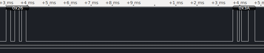
The following is the captured power off command (0x26) which is always followed by a lamp driver reset command (0x3A).
So the lamp ballast control can be easily turned on and off by simply sending 0x25 and 0x26 via UART. The querying commands are not necessary if the goal is just to power on the lamp.
In fact, the lamp can be turned on more easily and no serial communication is required. According to OSRAM’s standardized UART protocol application note, the SCI signal has a higher turning on priority than the UART software command. This means that we can assert the SCI pin (pin 4) to turn on the lamp instead of issuing UART command to pin 5. And turning off the lamp is just a matter of removing the power. Depending on your particular situation, either way can be used to turn the lamp on and off. While asserting the SCI pin is simpler, using UART commands gives you a lot more flexibility if your goal is more than just on and off control.
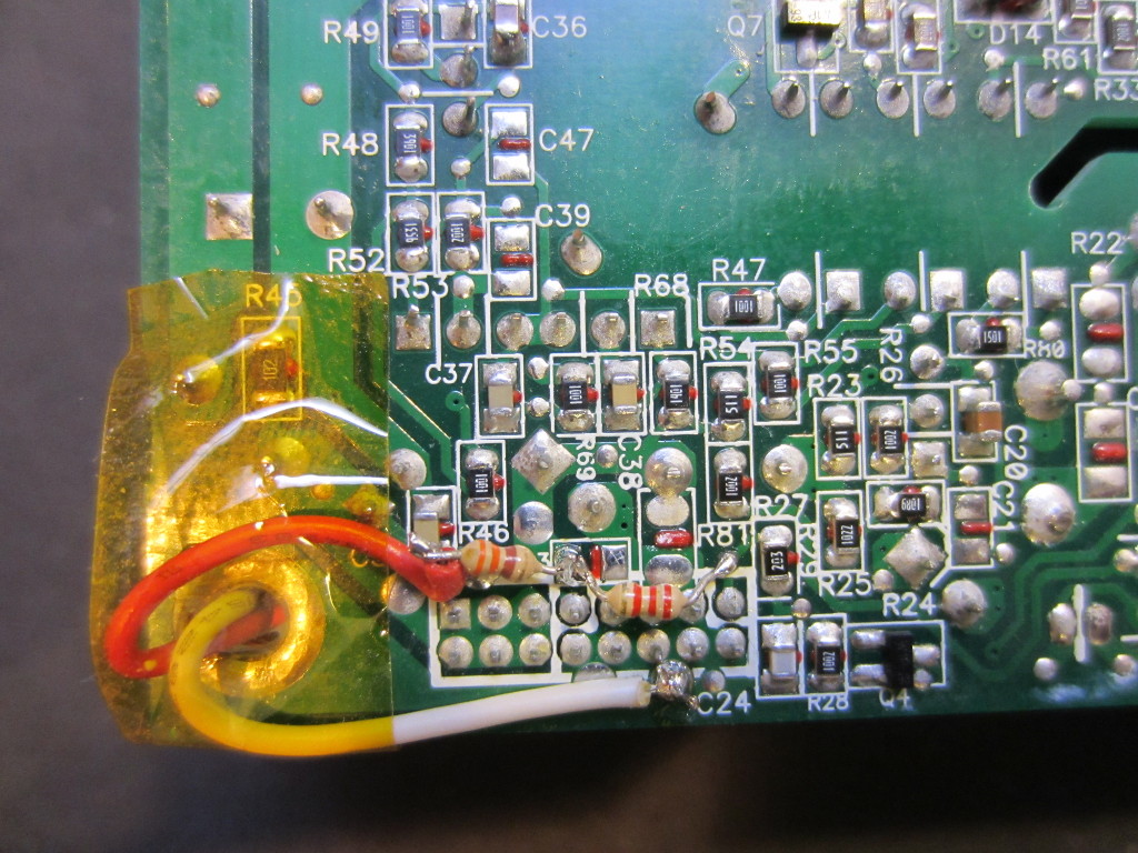
The main switching supply is controlled by the main board, so in order to operate without the main board, the power on pin needs to tied to 3.3V. So I connected a 2.2K resistor between the 5V stand by power pin (this voltage is always present when the power supply is plugged in) and the soft power on pin. Given the internal resistance present, this resistor value drops the 5V by roughly 1.5V so we get the 3.5V on the power on pin.
Once the power on pin is turned high, the high voltage inverter begins to work and the output from the high voltage connector should be around 385V. To assert the SCI pin (pin 4) on the P-VIP controller, we need a current limited 5V to turn on the photo diode (the photo diodes are common anodes, which means 5V needs to be applied to the common pin and the power supply ground needs to be connected to the SCI pin). This is achieved via a 330 Ohm resistor connected to the 5V rail. Note that this only works because the supply output does’t not share a common ground with the P-VIP controller board. Otherwise, an external power supply would be needed.
Here is a picture showing the minimum number of connections required to power the discharge lamp.
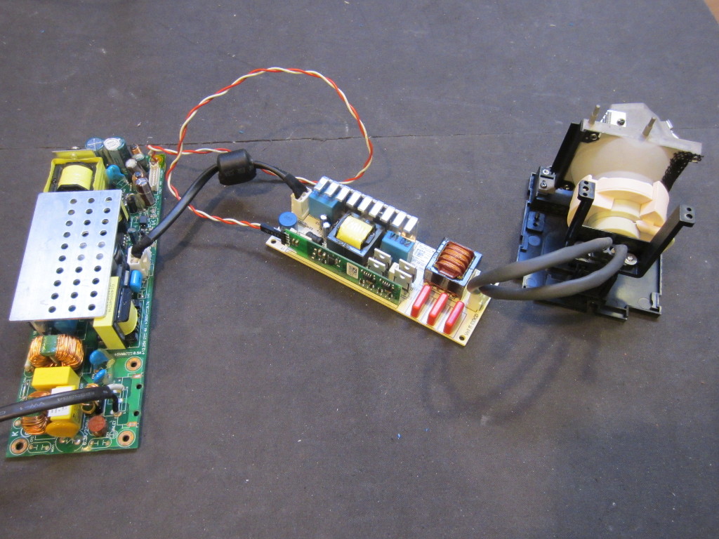
And here is a video showing the lamp in action.

