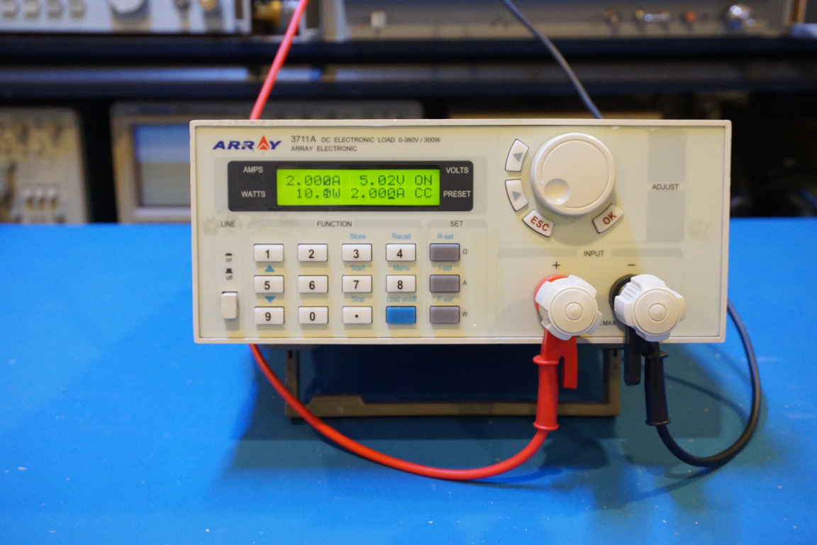
I have made many electronic loads in the past. For instance this simple harddrive cooler housed small dummy load, this more sophisticated constant current/constant programmable load and this heavy-duty electronic load that is capable of sinking over 1kW under peak load. In this blog post though, I am going to take a look inside an Array 3711A DC electronic load I recently purchased on eBay. You can find a video of this teardown towards the end of the post.
The Arrary 3711A can sink 300W with a maximum load current of 30A and maximum load voltage of 300V. It can be used in constant current, constant power or constant resistance mode and can be controlled remotely via an RS232 interface.
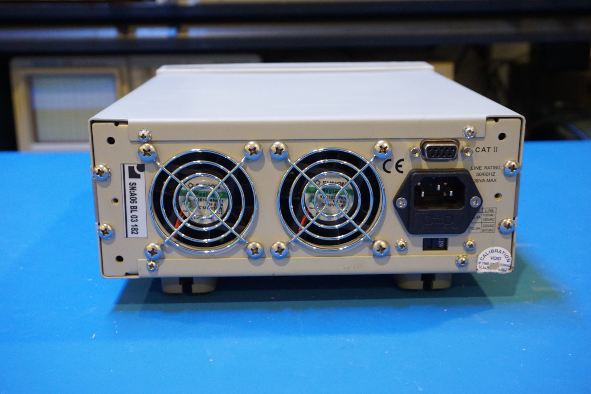
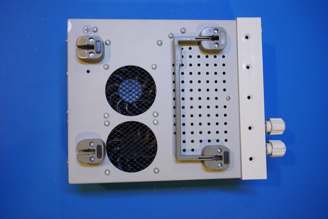
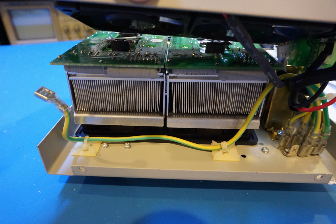
The entire unit is actually quite compact given the amount of power it is capable of dissipating. This can be largely attributed to the efficient forced-air cooling system it uses. There are four fans all together. Two are sitting at the bottom of the chassis that sucks in air. The air then flows through the heatsinks and the hot air gets blown out from the back via another two fans.
|
|
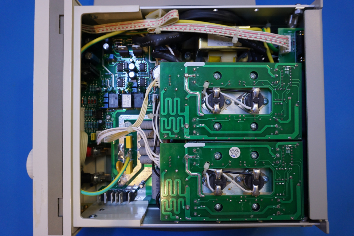
To achieve this compact design, some sacrifices need to be made. This becomes apparent after opening up the top cover. As you can see in the picture below, the power module boards are mounted directly on the heatsinks and the microcontroller board is tucked away behind the front panel. And to access any components located on either the front panel digital board or the analog board located at the bottom of the case you have no choice but to partially dissemble the unit.
And this is exactly what I did. Taking out the front panel is not quite trivial as it turned out. The front panel binding posts are screwed onto the connectors that are soldered onto the bottom board. Getting to these nuts are not easy given the tight clearance. With quite a bit of effort, I was able to eventually take out the bottom main board for a closer look.
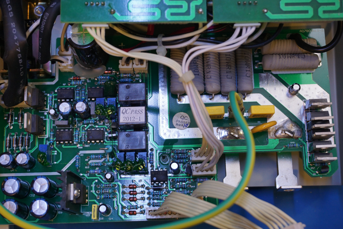
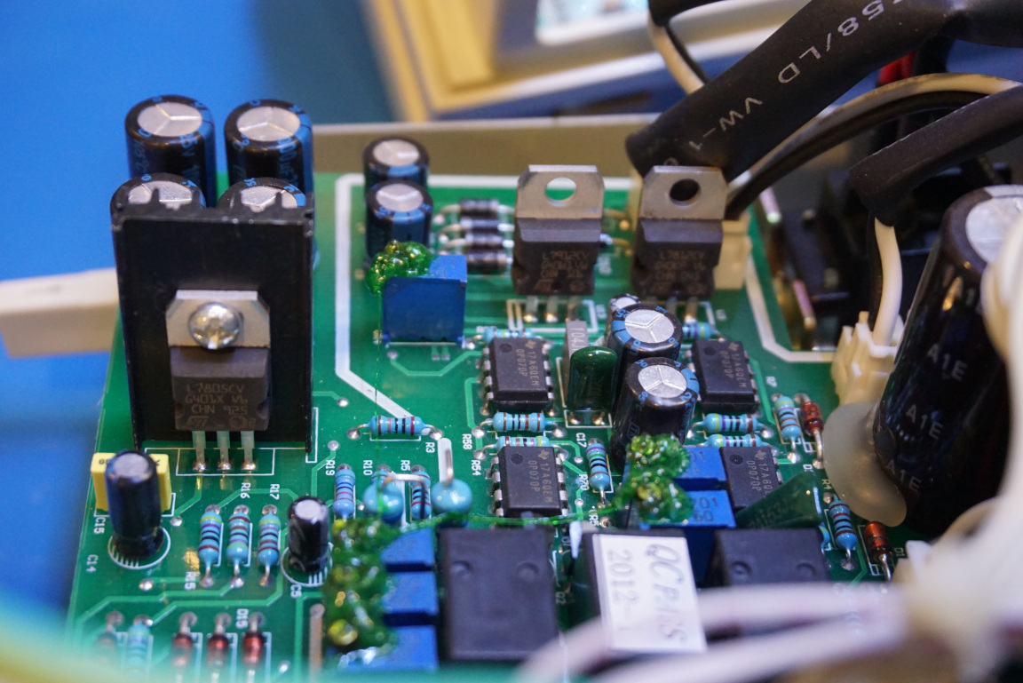
In the picture to the left below, you can see most of the components on the board. The main OpAmps used in the 3711A are OP07 ultra-low offset voltage OpAmps. There are three relays in the unit, two appears to be controlling the input voltage and current sensing and one controls the six paralleled IRF3205 which switch the load on and off. Quite a few of the wire-wound power resistors can also be seen.
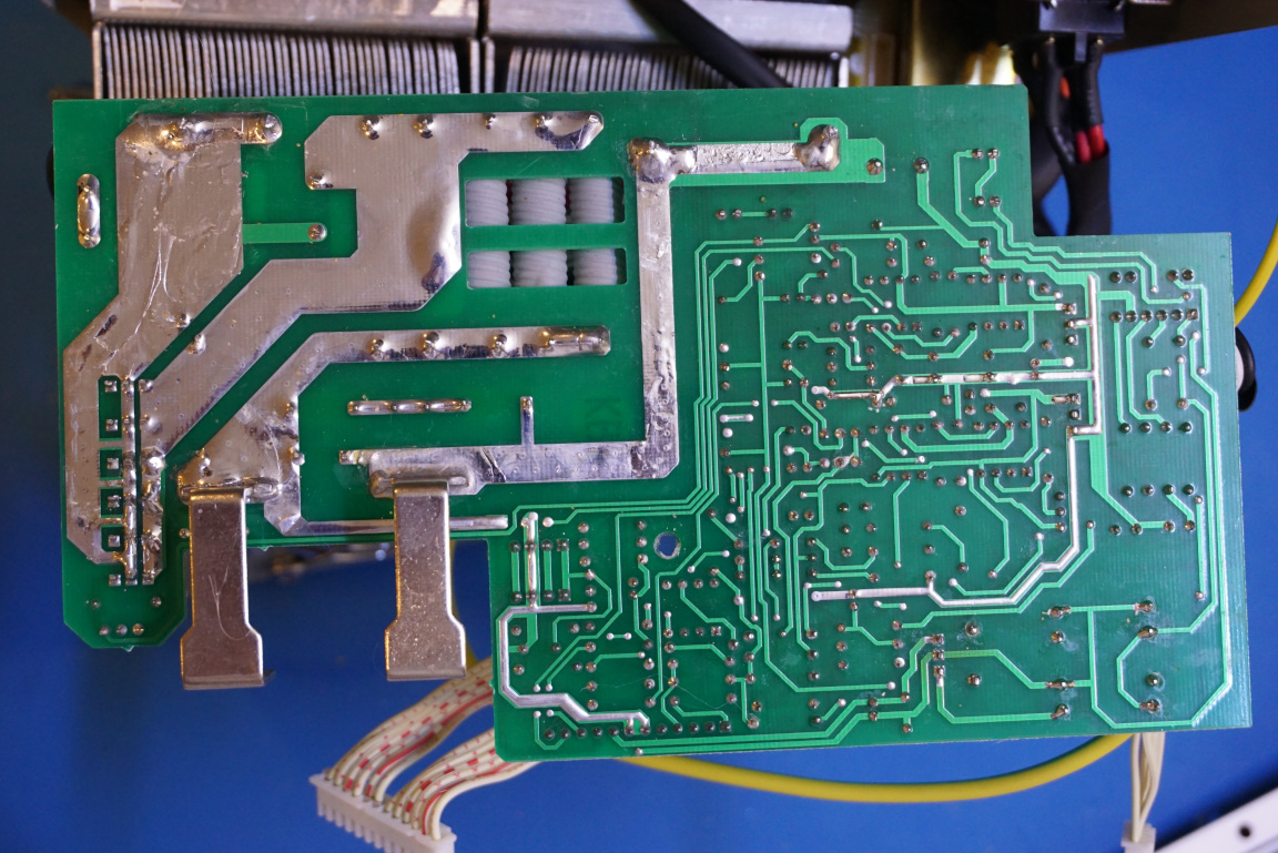
From the picture to the right below you can see that most of the current-carrying traces are via-stitched together from the top to the bottom layer of the PCB to reduce resistance and the traces are tinned as well.
|
|
The heatsinks used are relatively small given how much power they need to dissipate. There are two power modules, each has four IRFP460 power MOSFETs to share the load. In the 300W version (3711A), both modules are present whereas in the 150W version (3710A) only one module is used.
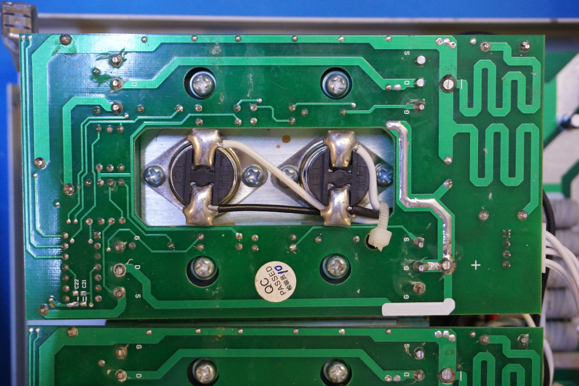
From the picture on the right you can see the thermal cut-offs mounted on top of the heatsink. They will shutdown the MOSFETs should the heatsink temperature becomes too high during operation. You can also see the snaked around traces, I believe these are used to match the current sensing resistance so that all four MOSFETs share the load current evenly.
|
|
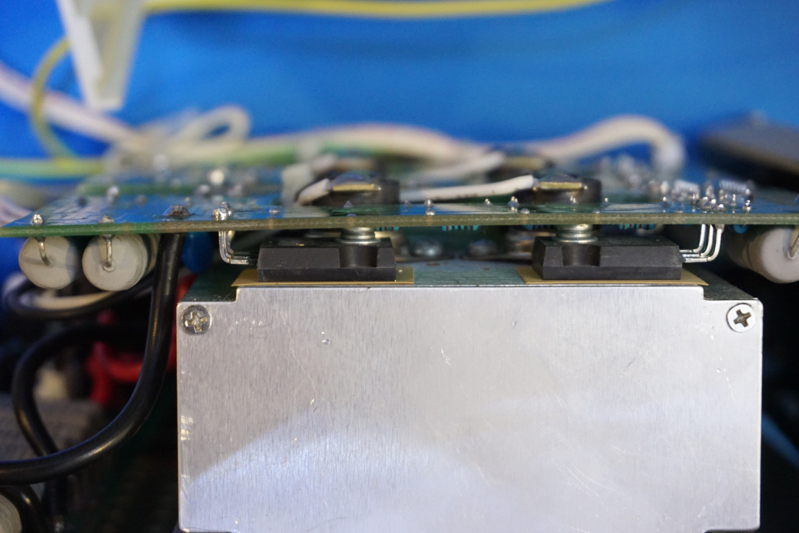
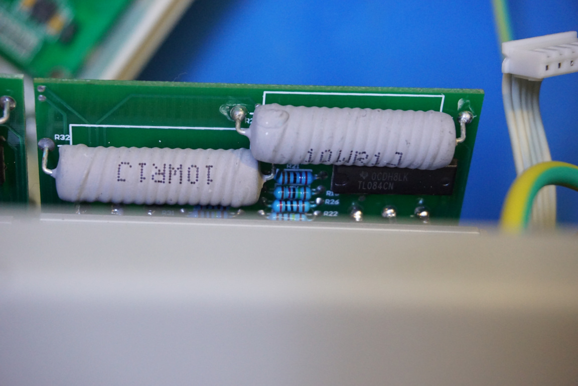
Here is a picture showing how the MOSFETs are mounted. They are folded over and soldered onto the board. This way, the space required for the power module is greatly reduced. I did not bother removing the MOSFETs off the heatsink and flip the board over as according to the schematics (they are included towards the end of the post), besides some resistors and a TL084 quad OpAmp which you can see from the picture to the right, there is not much else on this board.
|
|
Here is a picture showing the linear regulator portion of the board. The ±12V for the OpAmps comes from the 7812 and 7912 regulards and the 5V used by the digital circuitry is supplied from the 7805.
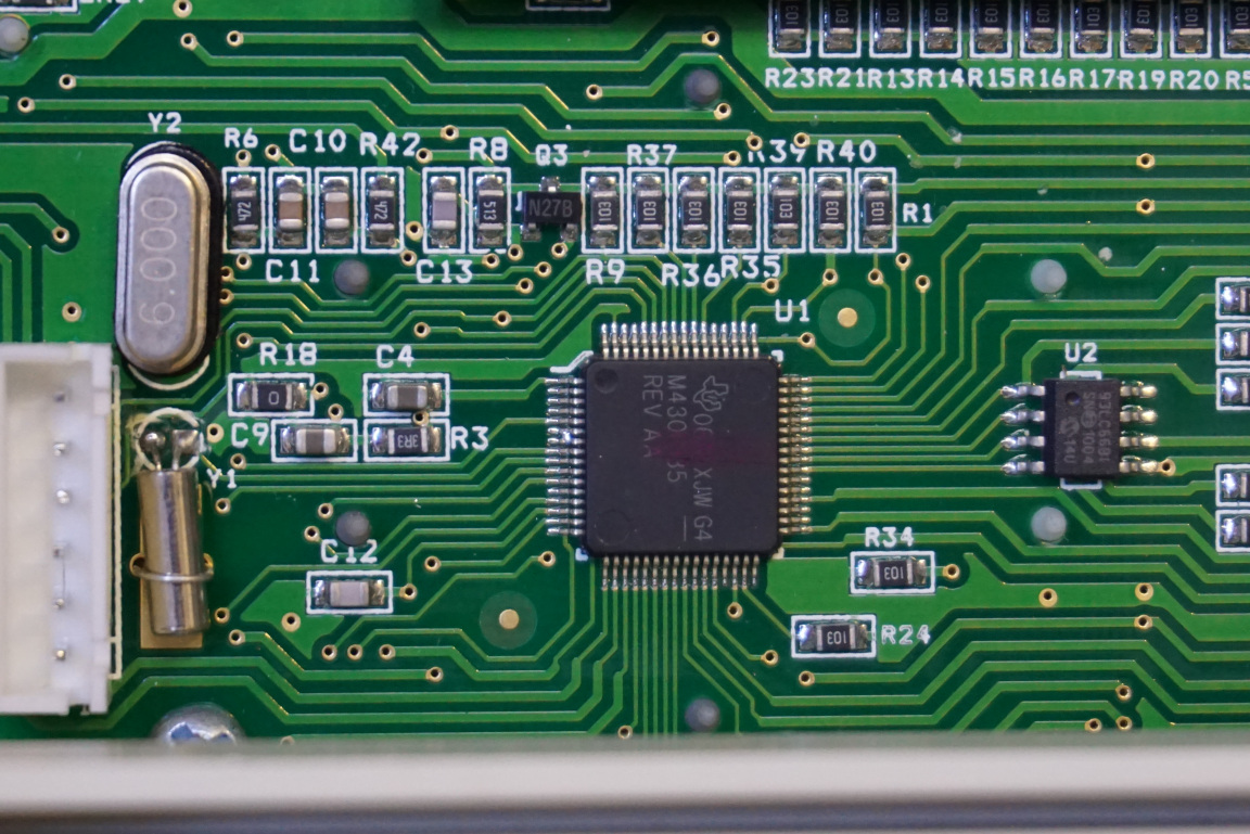
The front panel board houses the MCU, display and input keypad matrix. The vertical header in the middle is for programming the microcontroller. The LCD used in this unit is a standard 16×2 LCD.
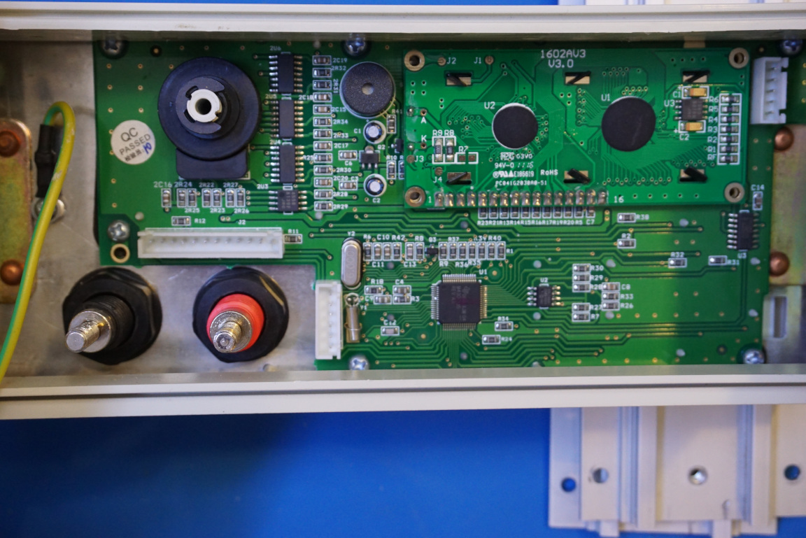
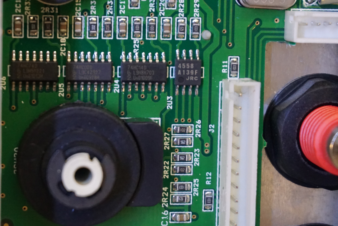
The microcontroller used in the Array 3711A is TI’s 16-bit MSP430F135. You can also spot a 93LC66 4K EEPROM which I assume is where the calibration information stored. In the picture to the right you can see the rotary encoder and some 74HC logic ICs.
|
|
Finally here is a video of the teardown.

