Gyroscopes nowadays are based on micro-electro-mechanical systems (MEMS) technology. They are low cost and extremely miniaturized. A device combing both a three-axis gyroscope and a three-axis accelerometers (sometimes these devices are referred to as 6DOF devices) such as the MPU-6500 for example can be had in a QFN package as small as 3 mm x 3 mm and under 1 mm in height. Before these MEMS devices gained mainstream popularity however, larger piezoelectric vibrating gyroscopes were used in many consumer electronics devices.
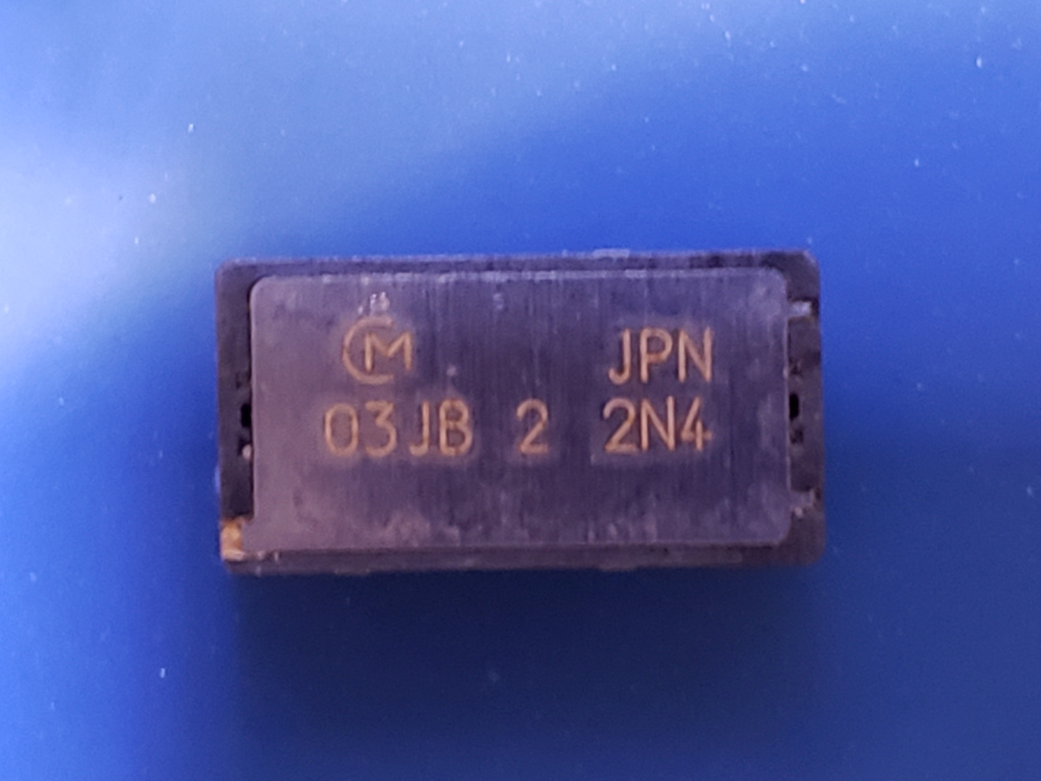
I was going through my component drawers and came across a couple of ENC-03J gyroscopes which were parted from an old Cannon ZR-65 miniDV video camera many years ago. Since each ENC-03J sensor is for detecting a single axis only, there are two sensors in the Cannon ZR-65 for detecting the rotation motions along two axes. According to the manual, the two gyroscopes chosen were operating under different resonant frequencies (ENC-03JA and ENC-03JB) to minimize mutual interference.
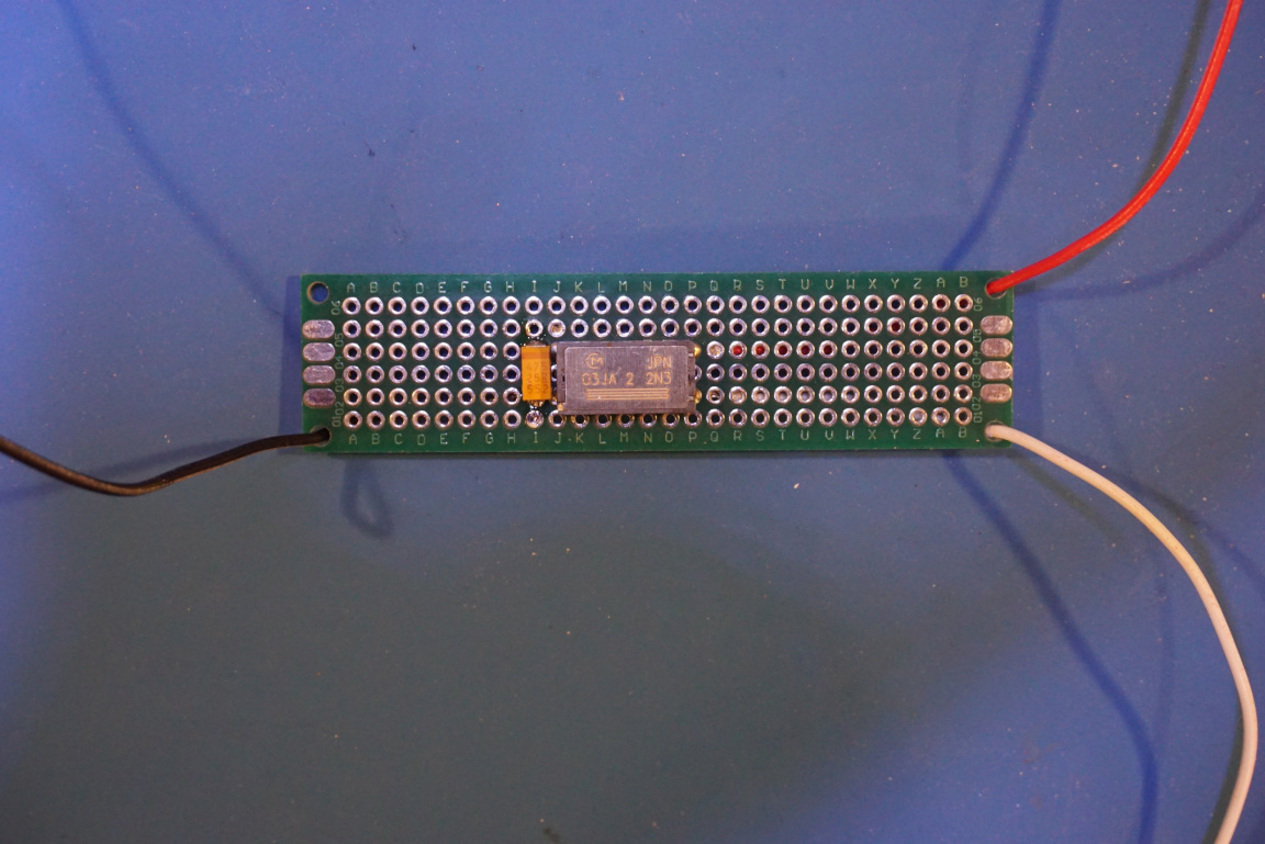
Verifying the performance of the ENC-03J is very straightforward. Since this is an analog gyroscope, there is only one additional wire for the signal output besides the power and ground connections. The picture below shows the minimum circuitry required for this gyroscope. A 4.7uf capacitor is soldered between the Vref pin and the ground as per the datasheet. And the output goes above or below the nominal 1.25V depending on the direction of the rotation. Typical application would require a bandpass filter at the output to limit the frequency component to between roughly 0.3 Hz to 1 kHz.
I was curious to see what’s encapsulated inside this ENC-03J gyroscope. Given it’s relatively large size (15.4 mm x 8 mm x 4.3 mm) I was pretty certain that this gyroscope was not based on MEMS.
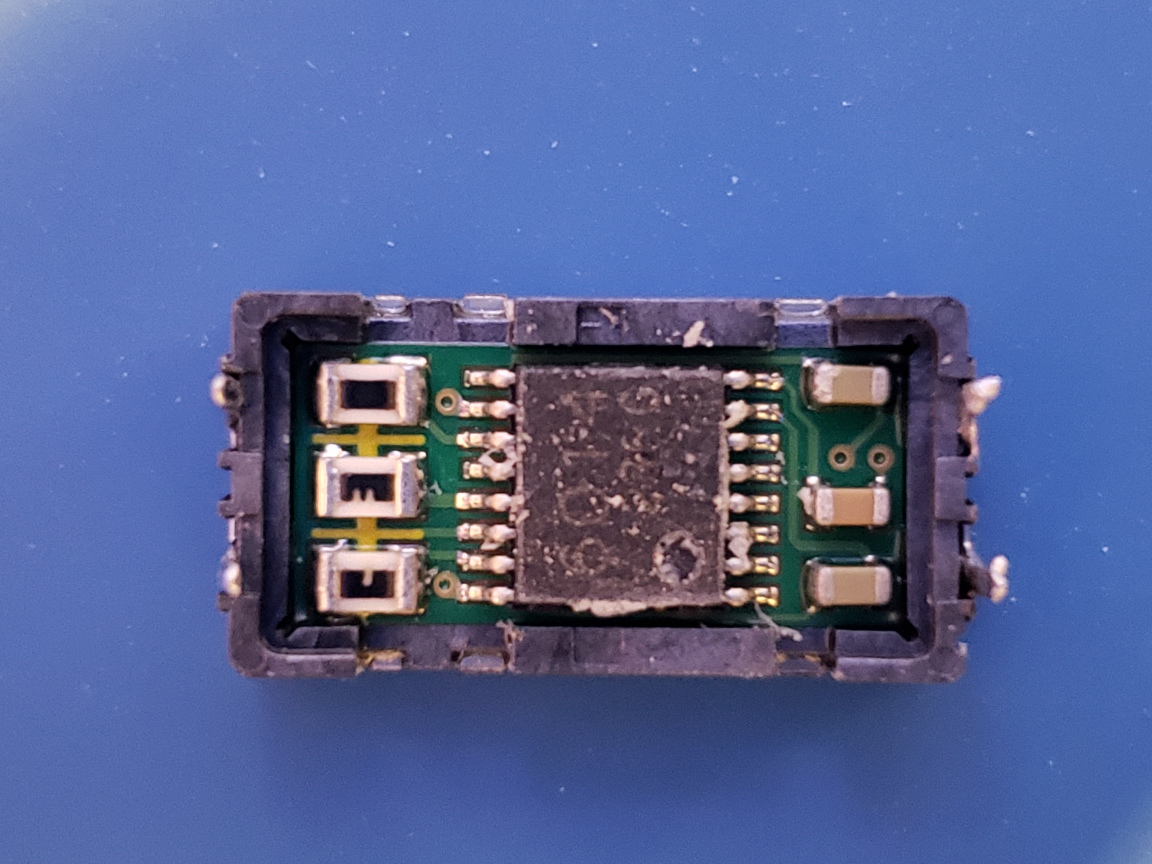
At first I was afraid that it might be difficult to open the package and in doing so might ultimately damage the components inside. But luckily, the package was very easy to open. In the picture below, you can see the package with the bottom cover removed.
In the center there is a 16 pin SMD chip with markings 6014 and 236G on top. I could not find any information on this chip but it is likely to be an OpAmp chip and possibly including an analog front end of some sort. Besides the IC, there are also three capacitors and three laser trimmed resistors.
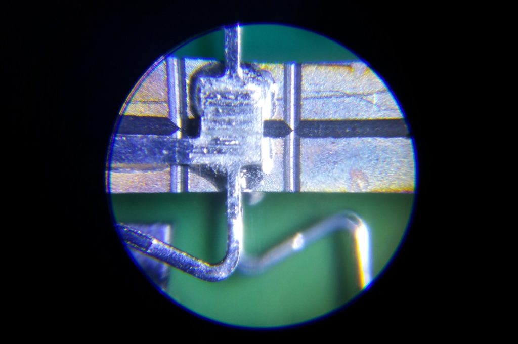
With the top cover removed, you can clearly see the ceramic piezoelectric bimorph structure that forms the heart of the sensing element. According to the datasheet, the principle of operation is as follows:
This angular velocity sensor employs the principle that a Coriolis force results if an angular velocity is applied to a vibrating object.
And this asserted force can be then measured and characterized to produce an voltage output that corresponds to the rate and direction of the rotation.
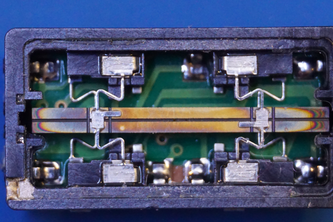
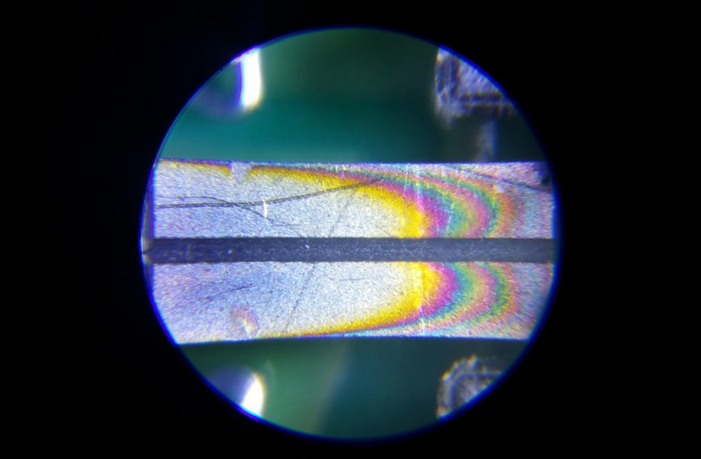
Here are a couple of closeup pictures showing the bimorph structure in a bit more detail. Note the coloration of the strips toward the end of the structure. Perhaps they were thermally treated? I am not entirely sure what the purpose it serves.
This type of vibrating structure gyroscope is sometimes also referred to as a Coriolis vibratory gyroscope (CVG).
In the video below, I walked through the testing and the teardown of the ENC-03J sensor. For the ENC-03JB that I did the teardown with I also measured the vibration frequency and it was at roughly 24 kHz which matches what was specified in the datasheet (the A version operates at 22 kHz according to the datasheet).

