Over the years, I have accumulated many used computer power bricks. Although I could just use them by themselves to power other electronics with similar voltage and current requirements, I thought I would combine a few of them together as the input to a linear regulator so that I can make a powerful lab power supply.
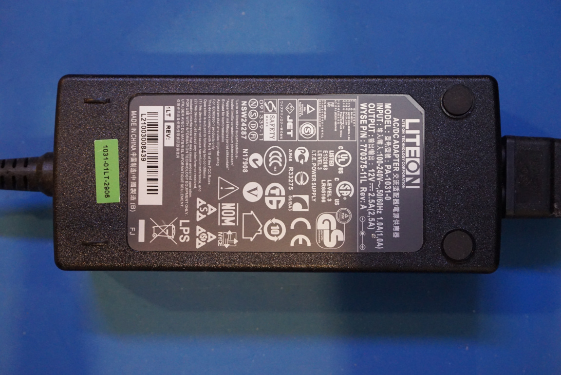
The power bricks I have in mind are these LITEON 12V/2.5A ones as I have quite a few of them lying around. I wanted to use a linear regulator as the output stage as linear regulators have superior power supply rejections and therefore can reduce the ripples introduced by the switching power supplies.
The linear regulator I wanted to use is an LM338, which is is perfect as I can use three of these 12V power bricks in series to achieve an 1.25V to 32V output range.
One of the main drawbacks of using a linear regulator is that the power dissipation is proportional the the input and output voltage difference. Given that the maximum power dissipation of the LM338 is around 25W, the maximum output current would be limited to under 1A in lower output voltage ranges due to the linear regulator power dissipation constraint. Also, each of these LITEON power bricks is rated for 2.5A maximum output current only while the LM338 is capable of handling up to 5A continuous output current. So two in parallel would be needed to utilize the full potential of an LM338.
To reduce the power dissipation in the linear regulator, we could switch in portions of the input voltages depending on the linear regulator output. For instance, when the output voltage is below 10V, we can use just a single 12V power brick. When the output is between 10V to 22V we can use two power bricks in series and thus putting out 24V. Finally, when the output is above 22V, we can switch in the last power brick and giving the linear regulator its full 36V input. This way the maximum voltage drop across the linear regulator is kept to be below 12V at all times, making it possible to deliver higher output current while still within the thermal limit of the LM338.
To increase the maximum current to above 5A, we will need to put two of these power bricks in parallel. An obvious solution is to use 6 of these power bricks in 3×2 configuration (three groups in series, each group with two in parallel). That’s a lot of power bricks! Most of the time however, I only needed higher current when dealing with lower voltage circuits therefore I could use a relay switching circuit to put two power bricks in parallel only when the output voltage is below 10V. The schematics below illustrates how we can implement this tri-range scheme using two relays.
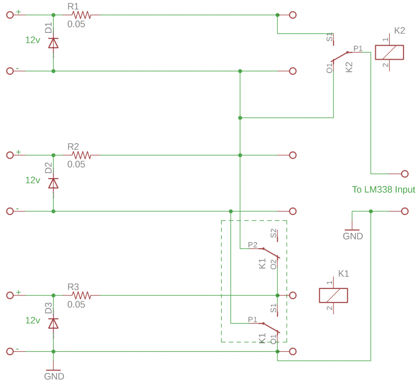
As you can see, at the default state K1 (a DPDT relay) and K2 (SPDT) are both switched off, P1 and P2 from K1 are connected with O1 and O2 and therefore the lower two power supplies are connected in parallel. The final output goes through relay K2 via O1 and P1 and forms a 12V input into the linear regulator. If we switch on K1 only, P1 and P2 are then connected to S1 and S2 respectively. Now the lower two power supplies are connected in series. Since K2 remains de-energized, the output still comes from the upper rail from the power supply in the middle and therefore the output becomes 24V. Finally, when both relays are switched on, the output from K2 would be via S1 and P1, essentially adding an additional 12V from the upper power supply to the output and therefore the voltage to the linear regulator would be 36V.
R1-R3 are load sharing resistors. Technically speaking only R2 and R3 are needed as only the lower two power supplies are connected in parallel. D1-D3 are reverse protection diodes, these are added to allow safe in-series operation of the power supplies. Without these diodes, in the event when the output becomes shorted, one or more of the “weaker” power supplies could become reversely biased and could be damaged.
By using a couple of comparators, we can easily set the desired switching threshold voltages for K1 and K2. For LM338, the maximum voltage drop is around 2.5V, therefore we can set the switching voltage for K1 at around 9.5V and the switching voltage for K2 at around 21.5V by adjusting R3 and R4. Here’s the schematic of the relay control circuit using an LM393 comparator.
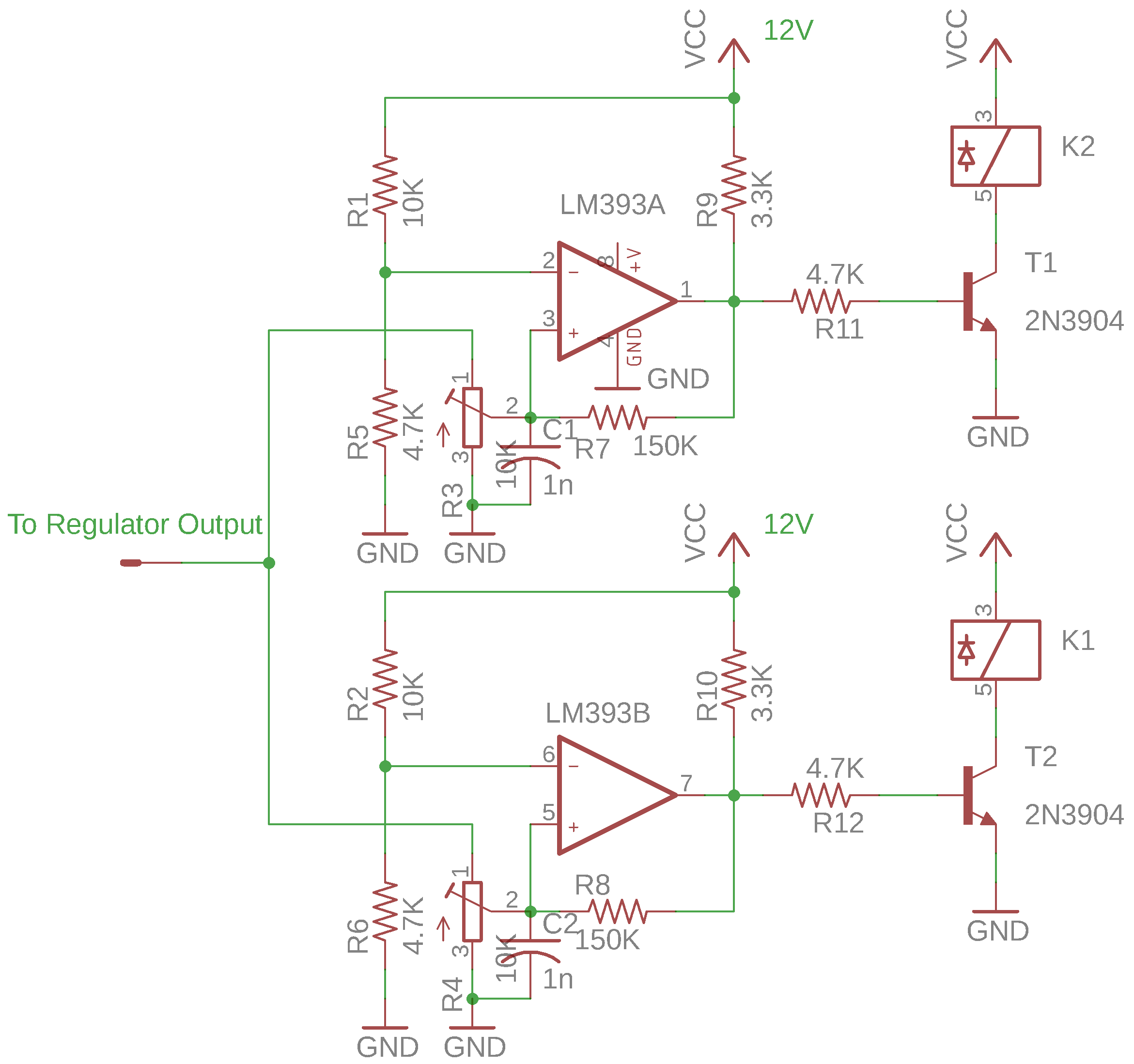
In the schematic above, the set voltages can be adjusted via trimmer R3 and R4. Note the small capacitors C1 and C2 between the comparator positive inputs and the ground. Since during the relay switching the output is briefly disconnected (break-before-make), without these capacitors the sudden loss of output voltage would cause these relays to switch erroneously. The added time constant ensures that these glitches are smoothed over.
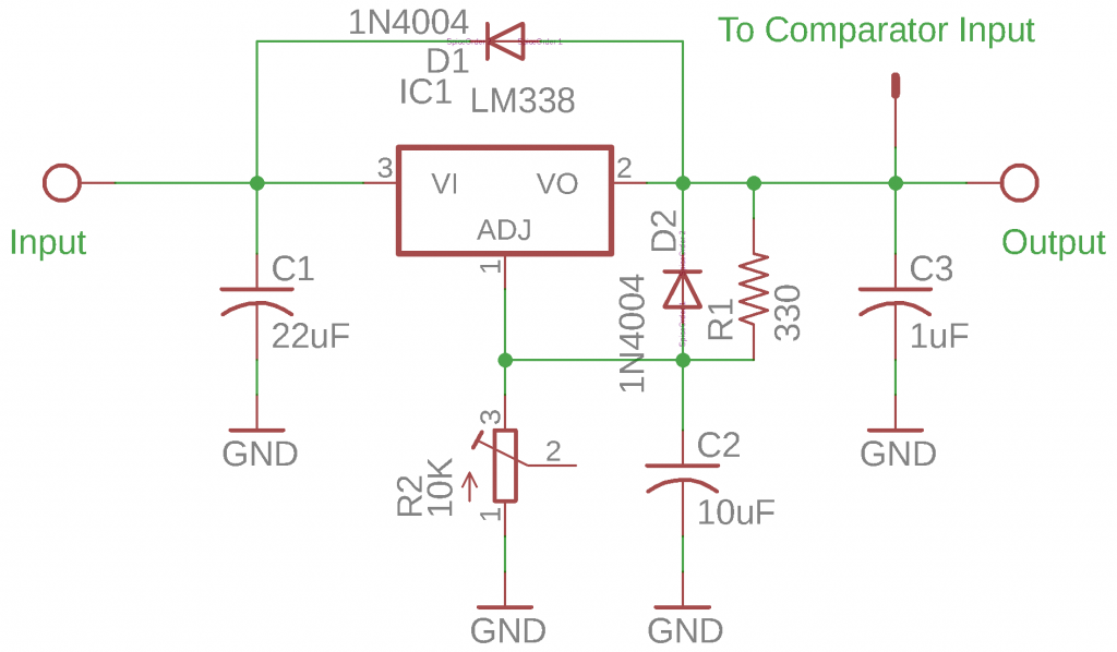
The circuit for the LM338 is rather standard. The values of R1 and R2 are chosen here to allow the output to cover the 1.25V to 32V range. As a side note, given that the comparator input is tied to the output of the linear regulator, range switching may not happen correctly under load. This is also due to the fact during range switching the input to the regulator is disconnected momentarily due to the break-before-make nature of the relay. This issue can be alleviated by increasing the value of C1. Given that many power bricks don’t like large capacitors at their outputs due to the momentary short created, increasing the value of C1 may not be an option. The easiest way to get around this limitation is to connect the load after the desired voltage has been established.
With the controlling circuitry sorted out, let’s take a look at the power brick themselves. Depending on the power bricks, the outputs are either isolated or ground referenced. In the case of these LITEON power bricks, the output negative terminal unfortunately is tied to earth ground. We would need to isolate the output ground from earth ground before these power bricks can be connected in series.
These LITEON power supplies utilize the fly-back topology (see pictures below, the one to the right is with the ground plane desoldered) and in principle the input and output are fully isolated. The only reason that the negative terminal is tied to the earth ground is for added safety (which is a very important reason!).
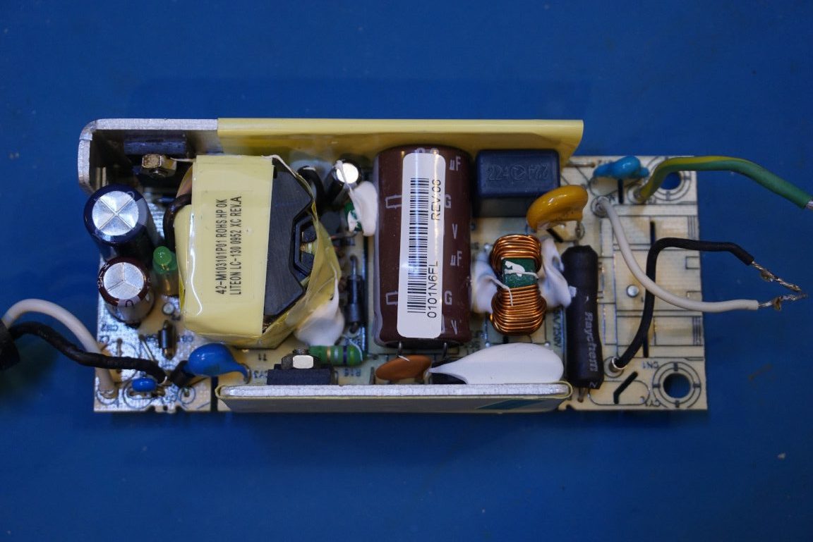
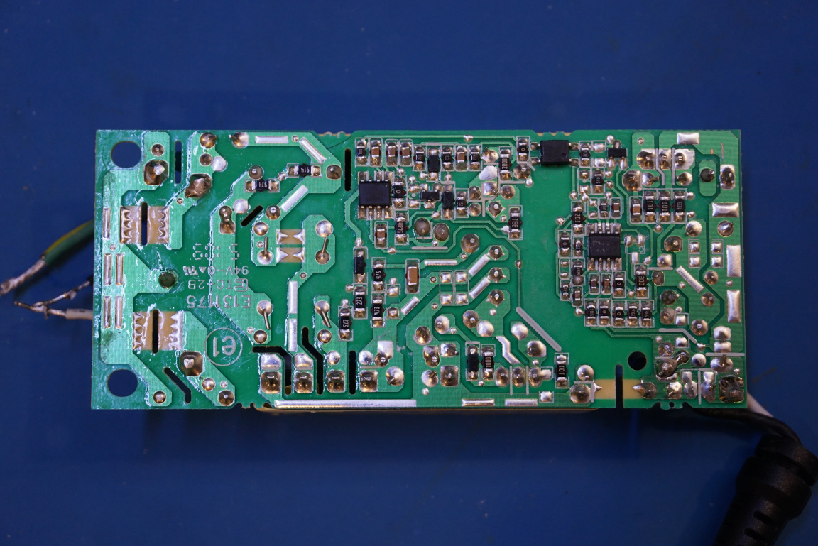
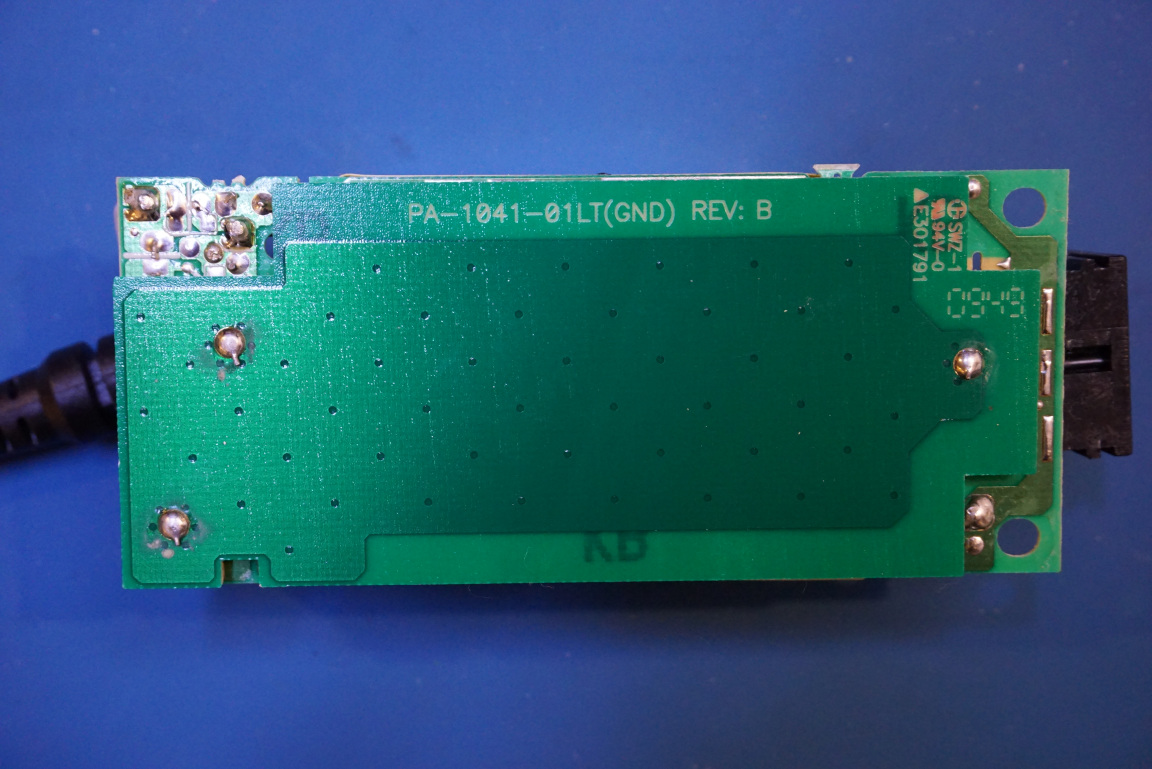
This power brick has a separate PCB dedicated as the ground plane and both the earth ground and the output negative terminal are tied to it. Besides serving as a ground plane, this extra PCB also protects the components on the back side of the main PCB. So instead of removing the ground plane, we can simply desolder the earth wiring from the three-prong socket.
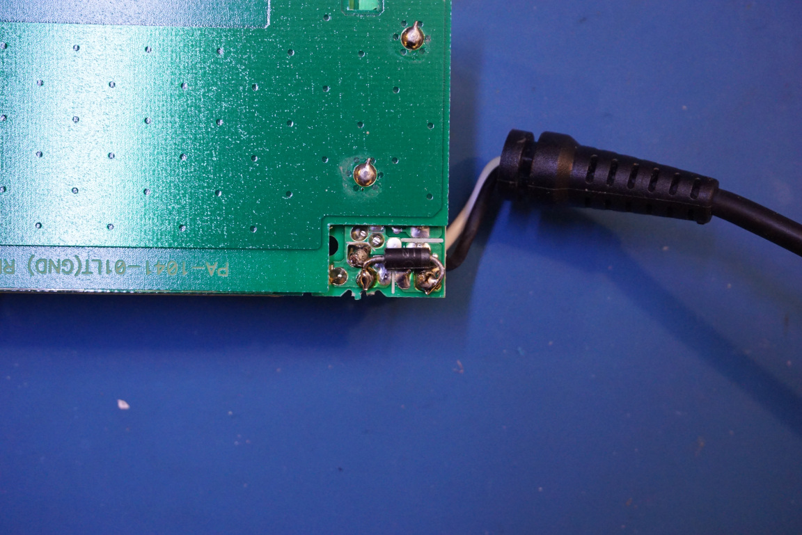
The picture to the left below shows the ground plane PCB. And the picture to the right below shows the added reverse protection diode.
Note that by removing the earth ground, we also removed one of the safety protection mechanisms. In the event that the primary and secondary of the pulse transformer becomes shorted for example, the output would become live and creating a very dangerous situation. A GFCI outlet should be used with these modifications to reduce the risk of electrical shock.
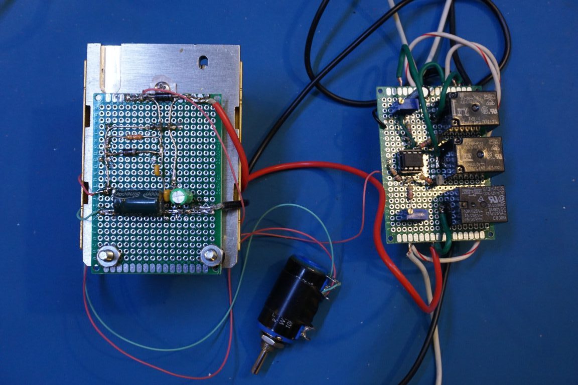
The picture below shows the completed circuitry on proto-boards. The linear regulator boards is on the left and the the relay controller board with the voltage comparator is on the right. The reason I used three relays instead of two is that I don’t have a double-pole-double-throw (DPDT) relay on hand at the moment, so instead two SPDT relays are used as a makeshift DPDT one.
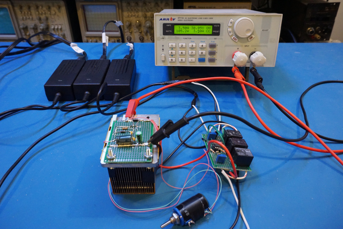
And here is a picture showing the completed setup.
Here is a video discussing the modifications to the power bricks needed in order to build this power supply.
In this video below, I walked through the finished circuit and did some load testing and demonstrated using relays to reconfigure the input power bricks to parallel and series modes.

