A while back I built a spot welder with an old microwave oven transformer (MOT). Since then, I have used it in many of my projects including using it to make a battery bank. While that spot welder does an excellent job, it is very bulky, so this time around I got a commercially available battery powered spot welder and wanted to see how well it works.
The spot welder I got is a BIFRC DH20 battery powered spot welder. It is quite popular because of its compact size, high output current and highly adjustable welding duration.
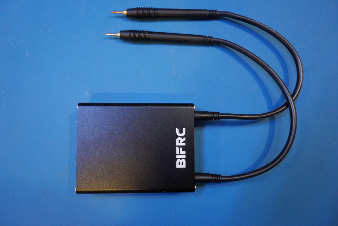
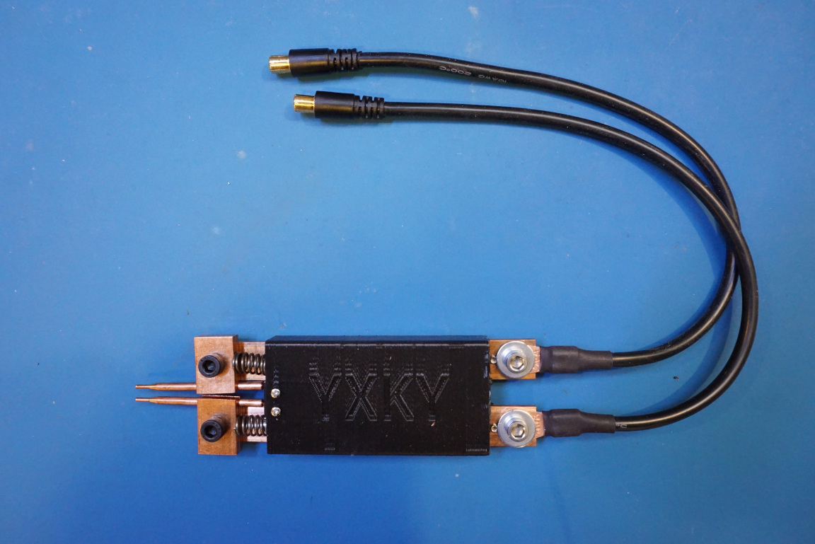
The unit I received comes with two sets of welding tips. One set is the pen style welding tips which is suitable for two-handed operations. The other set is a a YXKY branded assembly that is suitable for single-handed use.
One unique feature of this DH20 spot welder is that it does not have a separate switch to trigger the weld. Rather it senses when the welding tips are in contact of the welding material (e.g. nickle strips) and after a brief delay the weld is automatically initiated.
The principle of operation for a spot welder is conceptually very simple. A spot welder typically consists of a low internal resistance power source. This power source can be a low internal resistance Lithium Ion/ or Lipo battery cell, or it can be a super capacitor. Then you can switch on and off the output via a MOSFET or a group of paralleled MOSFETs to obtain the desired welding pulse duration.
In my MOT spot welder build, the switching happens on the primary side of the MOT and therefore it was less demanding to the switching element due to the lower current. But for a battery powered spot welder like the DH20, the switching is more critical as it happens along the main current path which in operation the peak current can reach over 1000A.
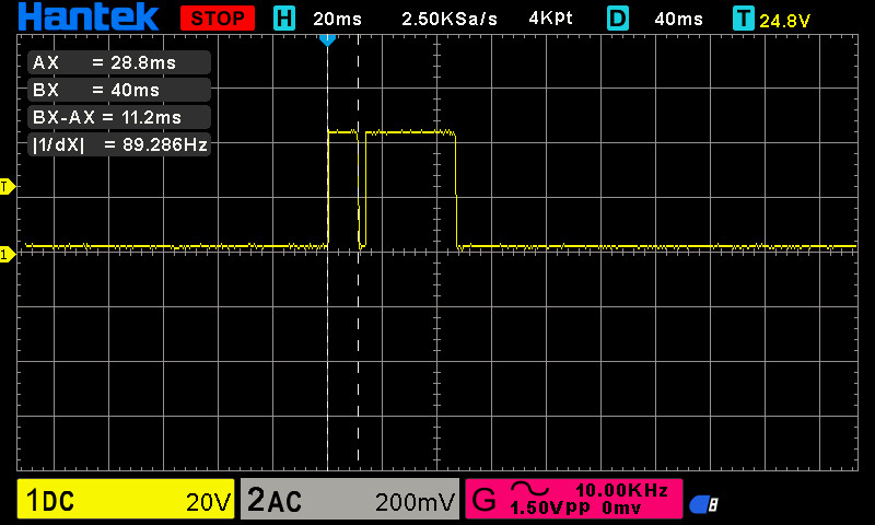
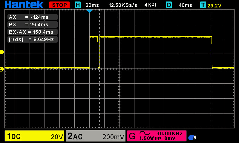
The DH20 has nine selectable welding durations, and the waveform consists of two separate pulses: a pilot pulse that is roughly 11ms in duration which is used to pre-weld the materials together. The secondary pulse which is delayed by 3ms , it is used to complete the weld. The width of the secondary pulse is selectable and can chosen from 30 ms to 150 ms at an interval of roughly 10 to 15 milliseconds per step. The oscilloscope captures below show the actual waveforms with the lowest duration setting (level 1):
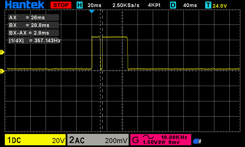

And here is the pulse waveform when the highest duration is selected (level 9). Note that the width of the pilot pulse and the spacing between the two pulses remain unchanged.
During operation, the pulse current measures at roughly 300A to 400A. You can check out the video towards the end and see it in action.
The circuit board can be easily removed from the aluminum enclosure after either of the panels is unscrewed.
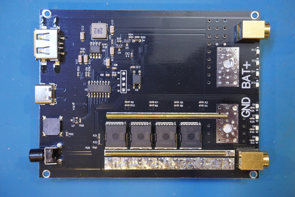
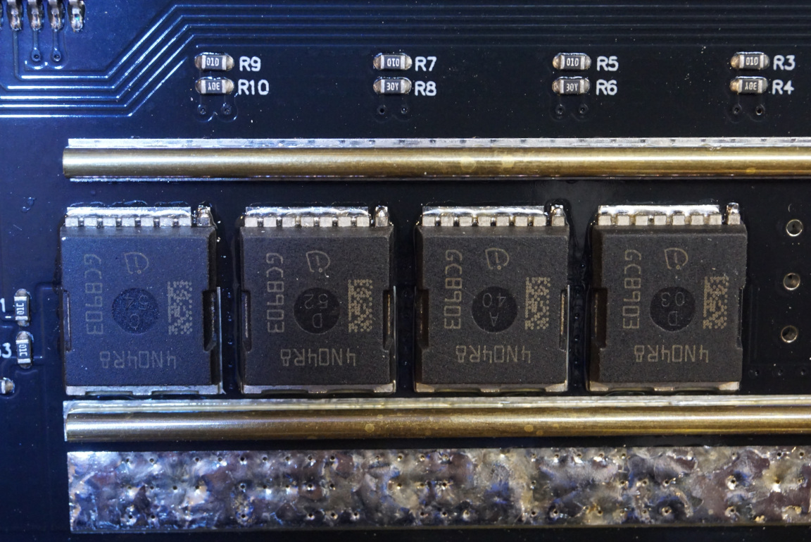
From the picture below, you can see the four paralleled switching MOSFETS. These are marked as 4N04R8 (I could not find an exact match of the datasheet) N-channel MOSFETs. The switch is placed on the low side of the circuit given the proximity to the ground terminal. The high current traces are reinforced with additional thick copper wires for the additional current carrying capability.
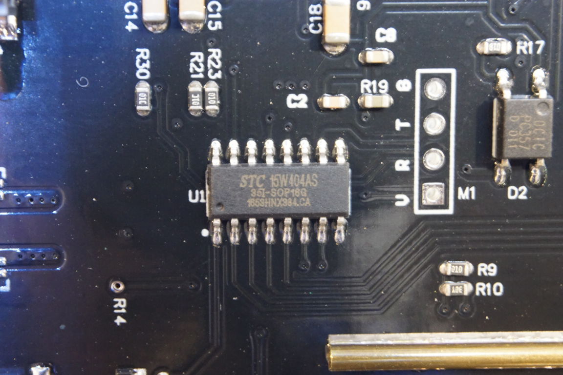
The main controller used is an 8051 based STC 15W404AS microcontroller. It has built-in 10-bit ADCs for voltage measurements. To the right side you can see an PC357 photocoupler.
The DH20 also has a 5V USB output so it can also be used as a battery bank. The charging circuitry and the 5V boost converter is handled by IP5306.
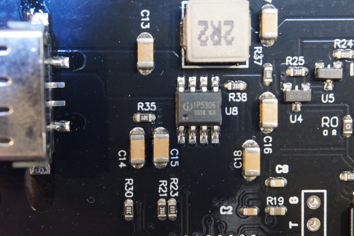
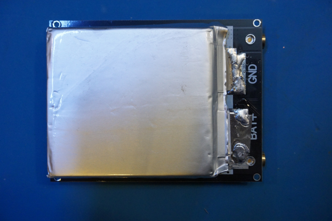
The Lipo battery is mounted on the reverse side of the PCB. You can see that the battery is soldered directly onto the PCB and the protection circuitry is not on the battery terminals. This is due to the large pulse current required during normal operation. So extreme caution needs to be taken when the circuit board is removed from the chassis. When discharging through the USB, the battery is protected by the IP5306 charging/discharging IC.
Here is a video detailing the analysis of this DH20 spot welder:

