I got my hands on a recently released Zotek ZOYI ZT-702S handheld digital oscilloscope. It is a combination of a 10 MHz bandwidth single channel oscilloscope and a 9,999 count digital multimeter packed in a single device. Compared to the many portable multi-functional oscilloscopes I have reviewed before, this one stands out on its price. At around $60, it is probably one of the cheapest handheld oscilloscopes I have seen.
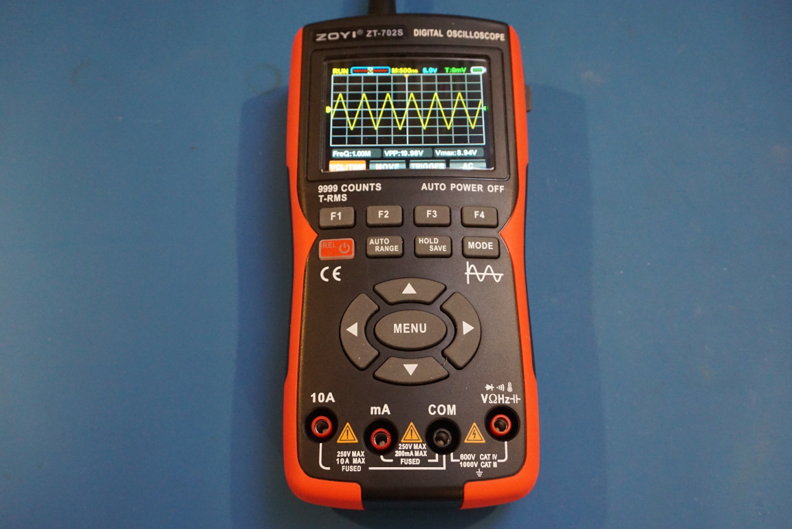
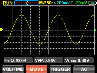
Don’t let the low price fool you, this oscilloscope performs very well even with its modest specifications. It has a surprisingly fast waveform update rate and achieved its full advertised 10 MHz bandwidth in my testing. It’s 64 K sample memory allows it to capture single shot waveforms. You can check out my review video to see more in details.
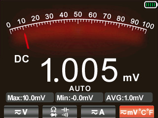
You can even take screenshots using this meter. This is a handy feature many will find useful especially in the oscilloscope mode.
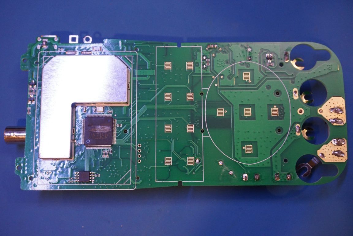
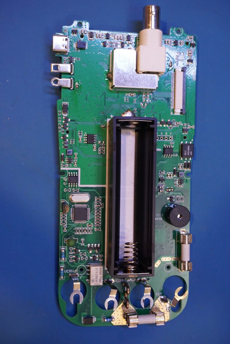
Here in this blog post though, let’s take a look at some of the teardown pictures.
The device is powered by a single 18650 Lithium Ion battery, the included battery has a capacity of 2000mA. At an operating current of around 315mA, this translates into almost seven hours of continuous use.
The input section is shielded. I did not desolder the shielding can, but underneath there is a range switching relay, a trimmer capacitor and a single transistor input stage.
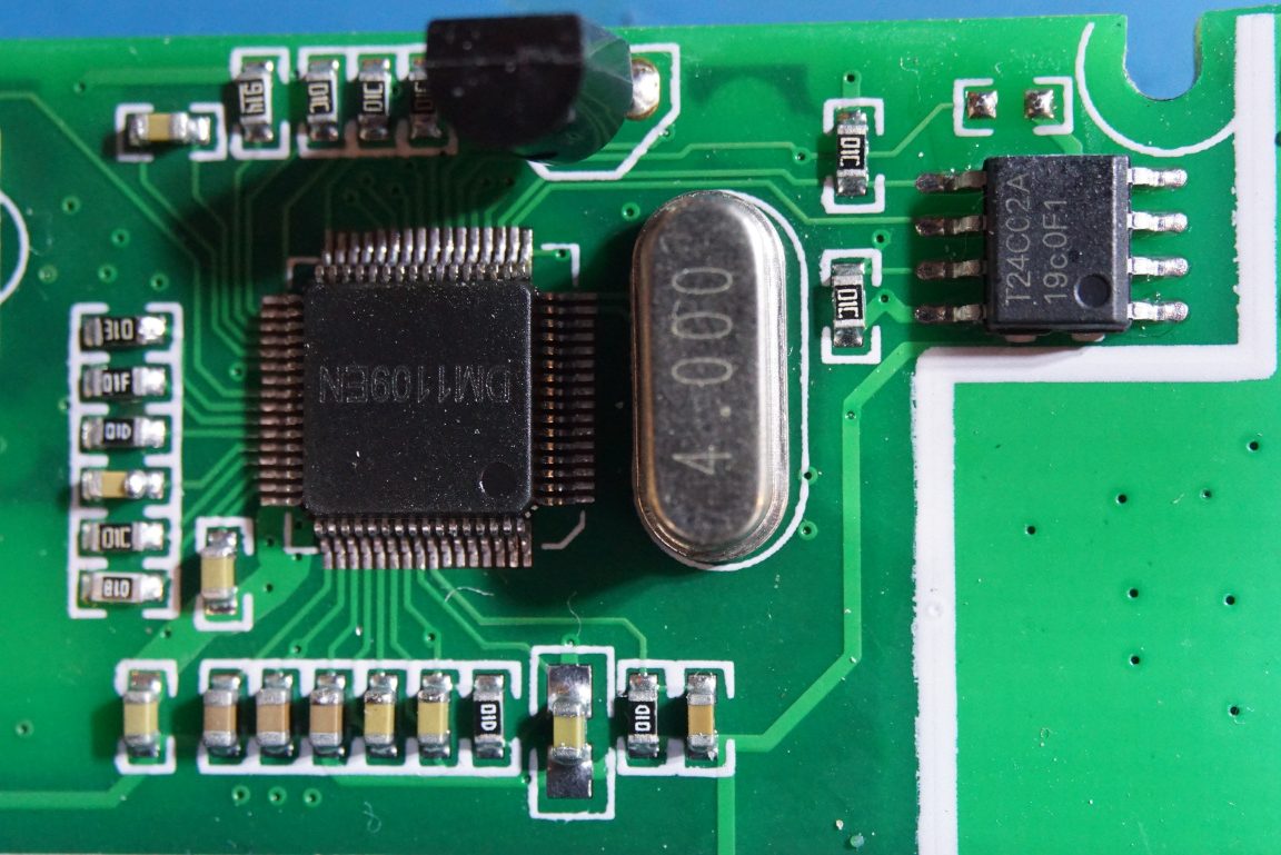
The DMM chip in use is a DM1109EN. There is not much information on this chip, but needless to say, it is a 9,999 counts multimeter IC. There 8 pin SOIC next to the crystal is an EEPROM chip for storing the DMM configurations and calibration constants.
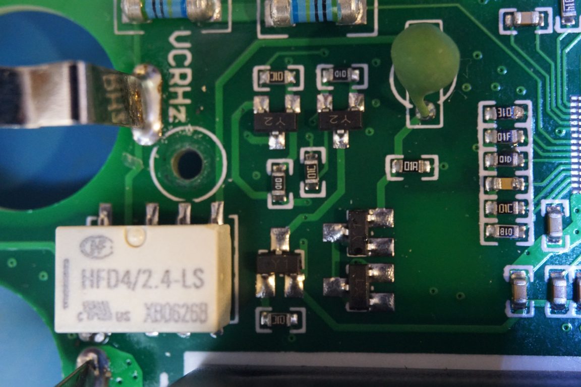
Like most cheap Chinese multimeters, there is not much input protection to speak of. There is only a single PTC along the input path for protection. And there are no MOVs. Although the meter is supposedly rated for CAT III 1000V and CAT IV 600V, I doubt that it actually meets these standards as the ratings are not independently verified. But for measuring household electronics, which are typically CAT II, this protection circuitry in this meter should be sufficient.
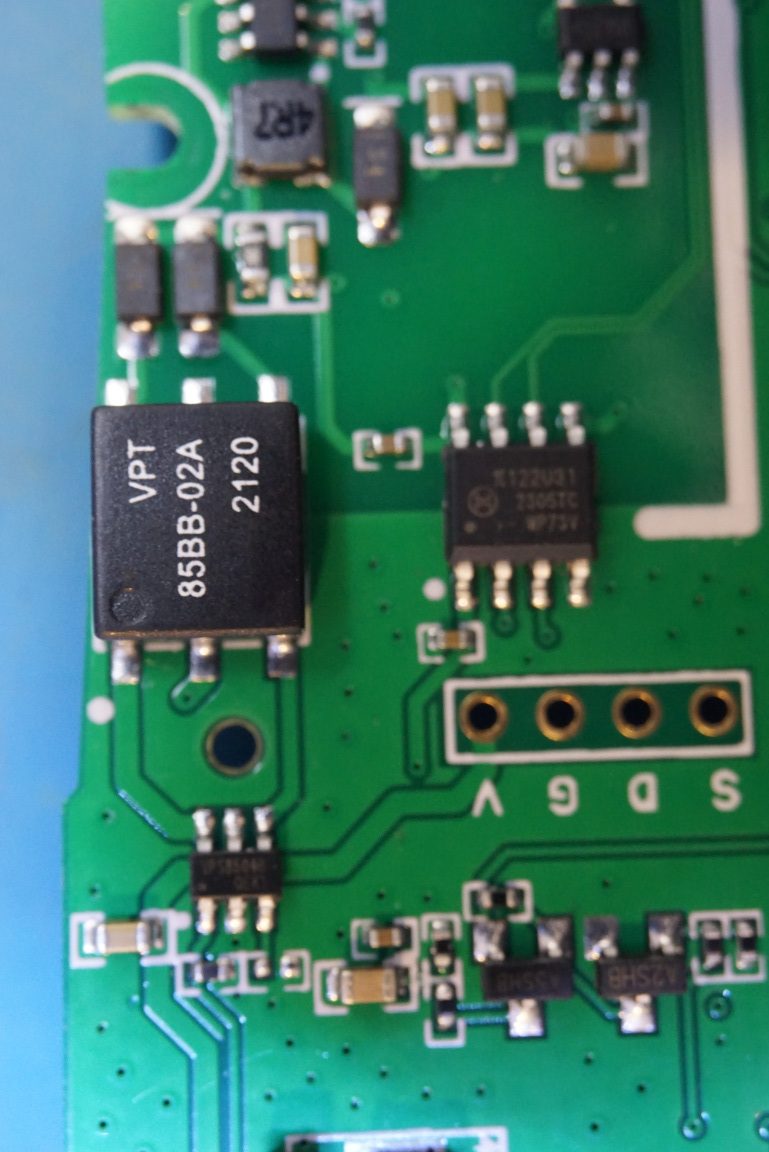
I am not sure what that six pin component marked with “85BB-02A” is in the picture below is. Nor could I find any information on the 8 pin chip beneath it. Given that these components are between the oscilloscope section and the multimeter section, they could be some kind of converter/isolator?
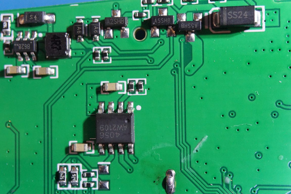
In the picture to the right below, there is a TP4056 Li-ion charger chip which is responsible for charging the onboard battery.
The main processor is an Artery ARM MCU. The marking unfortunately was sanded off so I was not able to tell the exact model. But other sources suggest that this is an AT32F-403, which has a powerful 32-bit Cortex M4 core.
The ADC is under the shielding. The ADC used in the meter is MS9280, which is a 10bit, 50MSPS ADC. This matches the maximum 48Msa/s sampling rate of the digital oscilloscope. The sampling output from the ADC is presumably stored into the SRAM in the MCU as there is no additional memory on board.