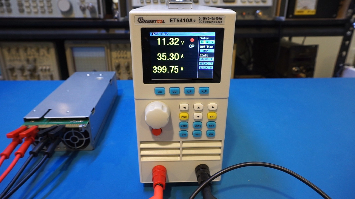
MUSTOOL ET5410A+ is a single channel programmable electronic load and battery tester. It is capable of sinking up to 40A of current and can dissipate up to 400W. The ET5410A+ can also be controlled remotely via PC. I did an extensive video review and teardown on this electronic load and a link is provided below. In this blog post, we will concentrate on the teardown and take a look at what’s inside.
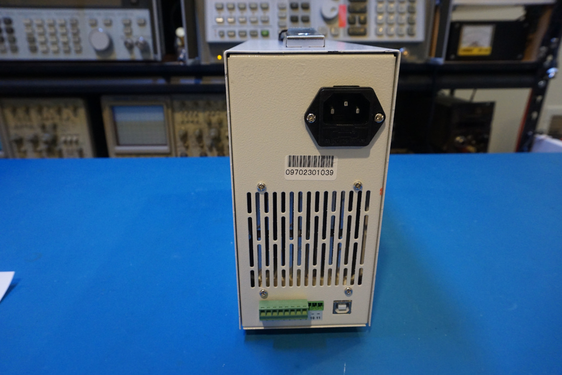
The ET5410A+ is relatively compact given its power dissipation specifications. All functionalities can be controlled via front panel buttons. PC communication can also be established using the USB port located on the back. As you can see in the picture to the right below, the unit also supports RS232/RS485 and other signaling through the provided input/output terminal block.
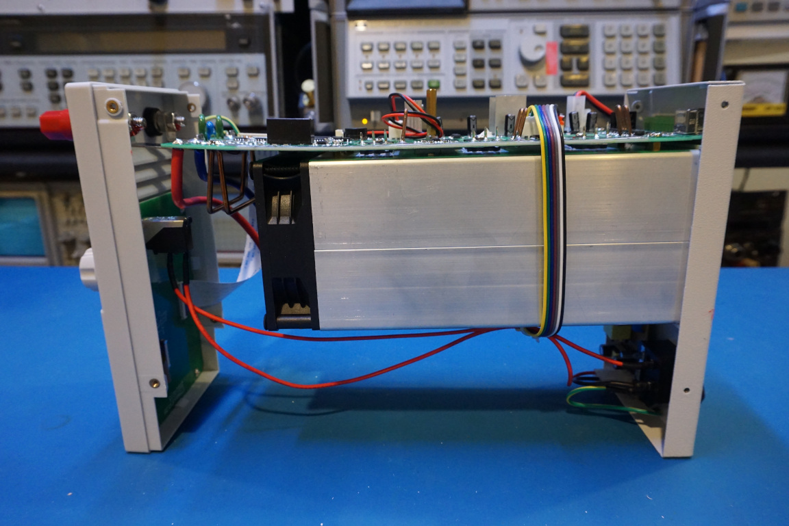
Upon opening the case, you can see that the circuit boards are essentially mounted around the main heatsink block. And this layout is what makes the overall dimensions of this electronic load so compact. Altogether, there are six power MOSFETs in this electronic load, three are mounted on the top side of the heatsink and the remaining three are mounted on the bottom side of the heatsink.
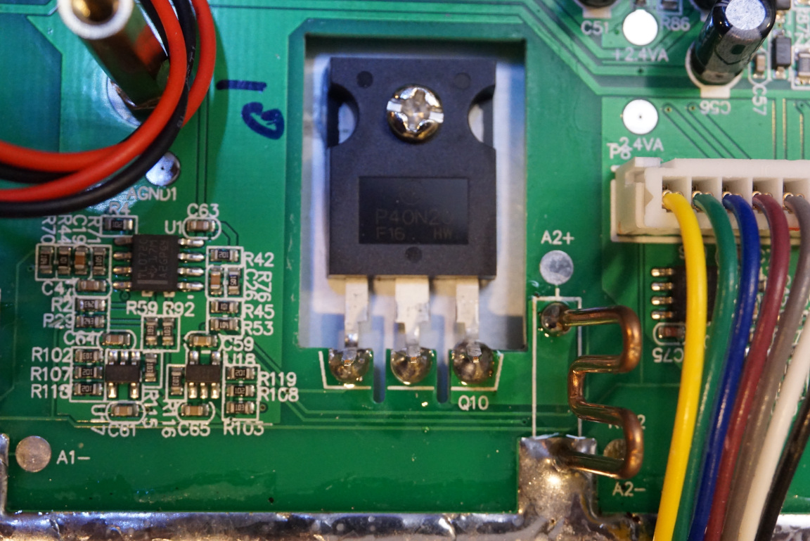
Note that the MOSFETs are mounted directly on the heatsink without any insulation pads. This improves the thermal conductivity but care must be taken especially when troubleshooting live circuit as the heatsink is essentially connected to the drains of the MOSFETs.
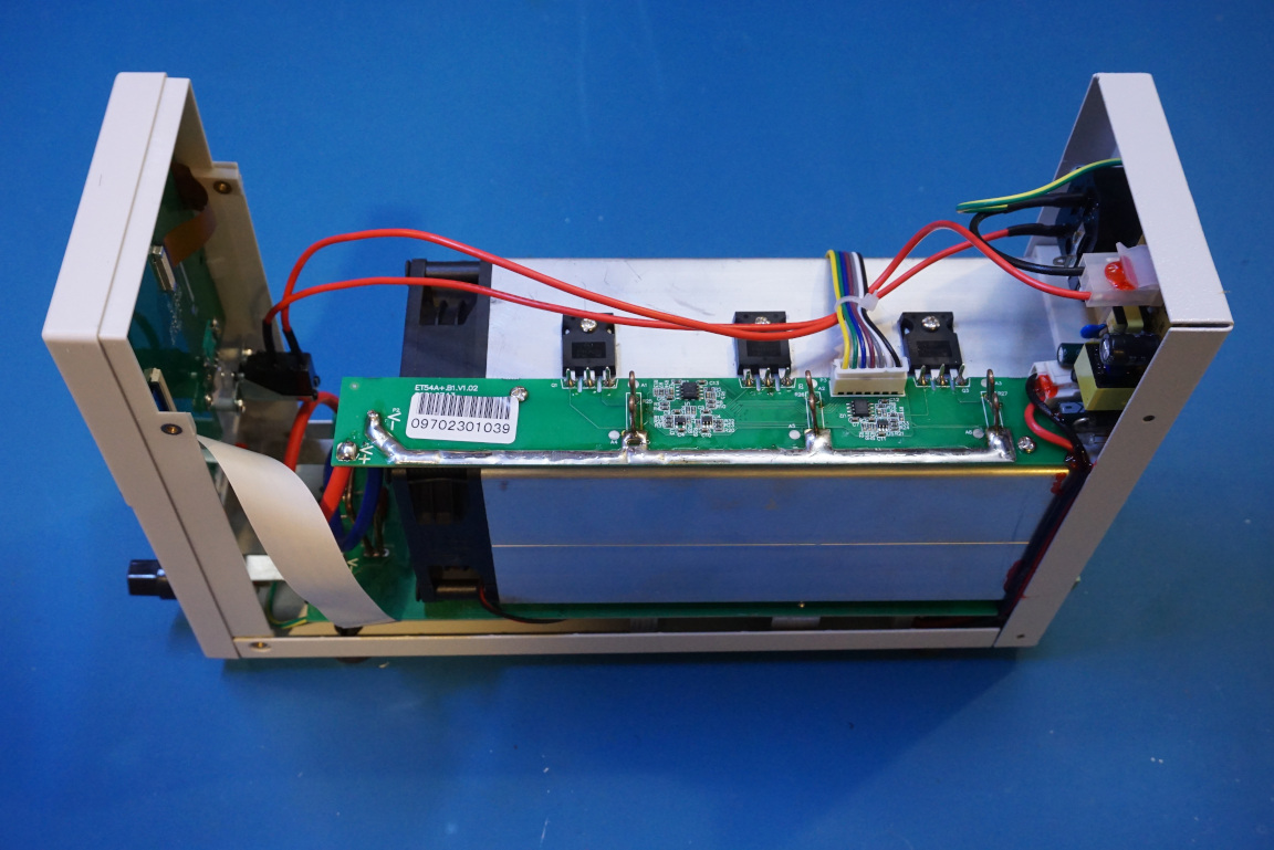
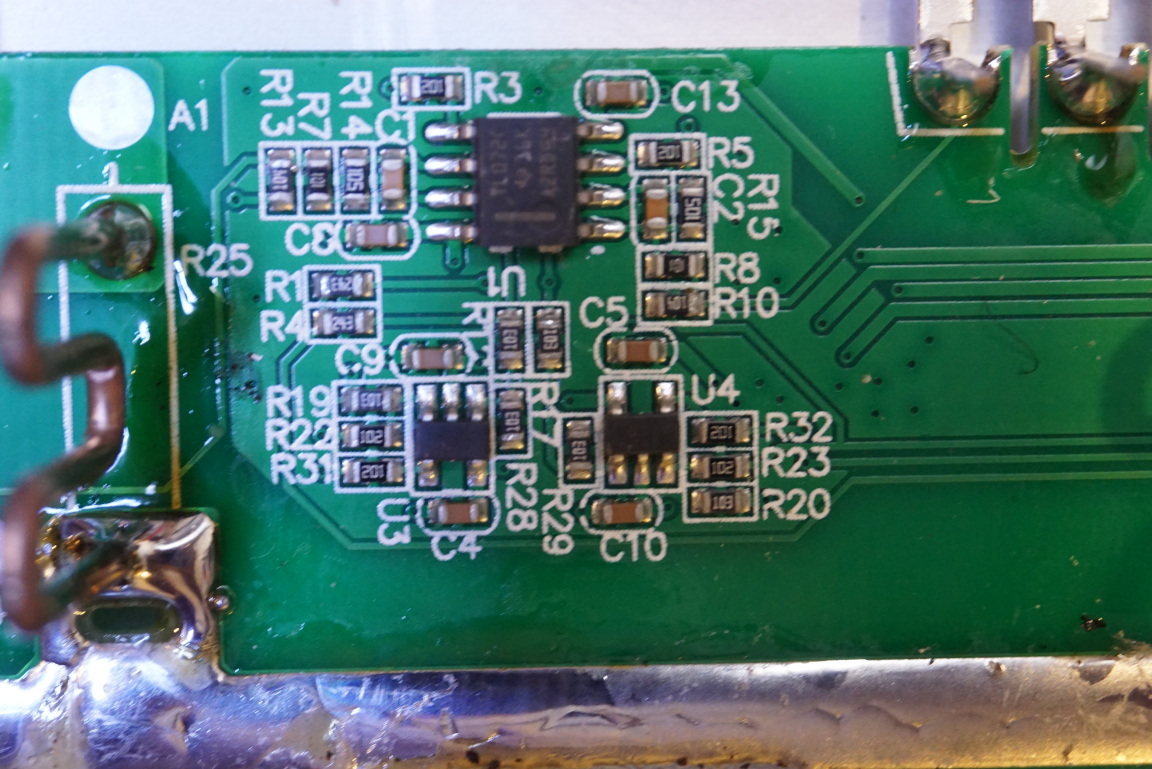
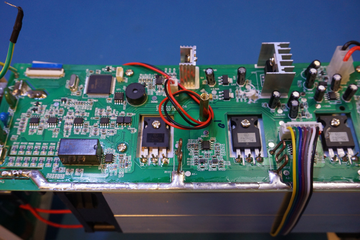
Each MOSFET is driven by an OpAmp (half of a dual OpAmp TL072). The smaller 5 pin devices (U3, U4) are presumably differential amplifiers for amplifying the voltage drop across the shunt resistors at the source of each MOSFET. The picture below shows the driving circuitry for two of the MOSFETs on the top side of the heatsink.
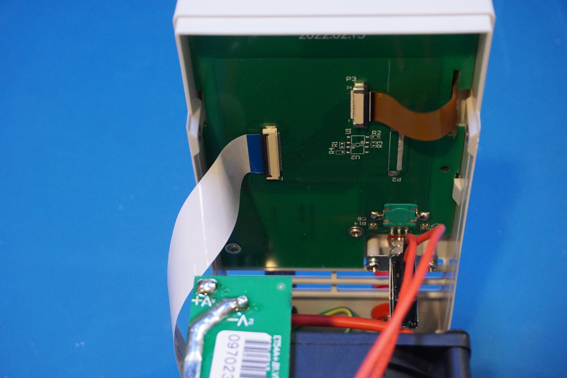
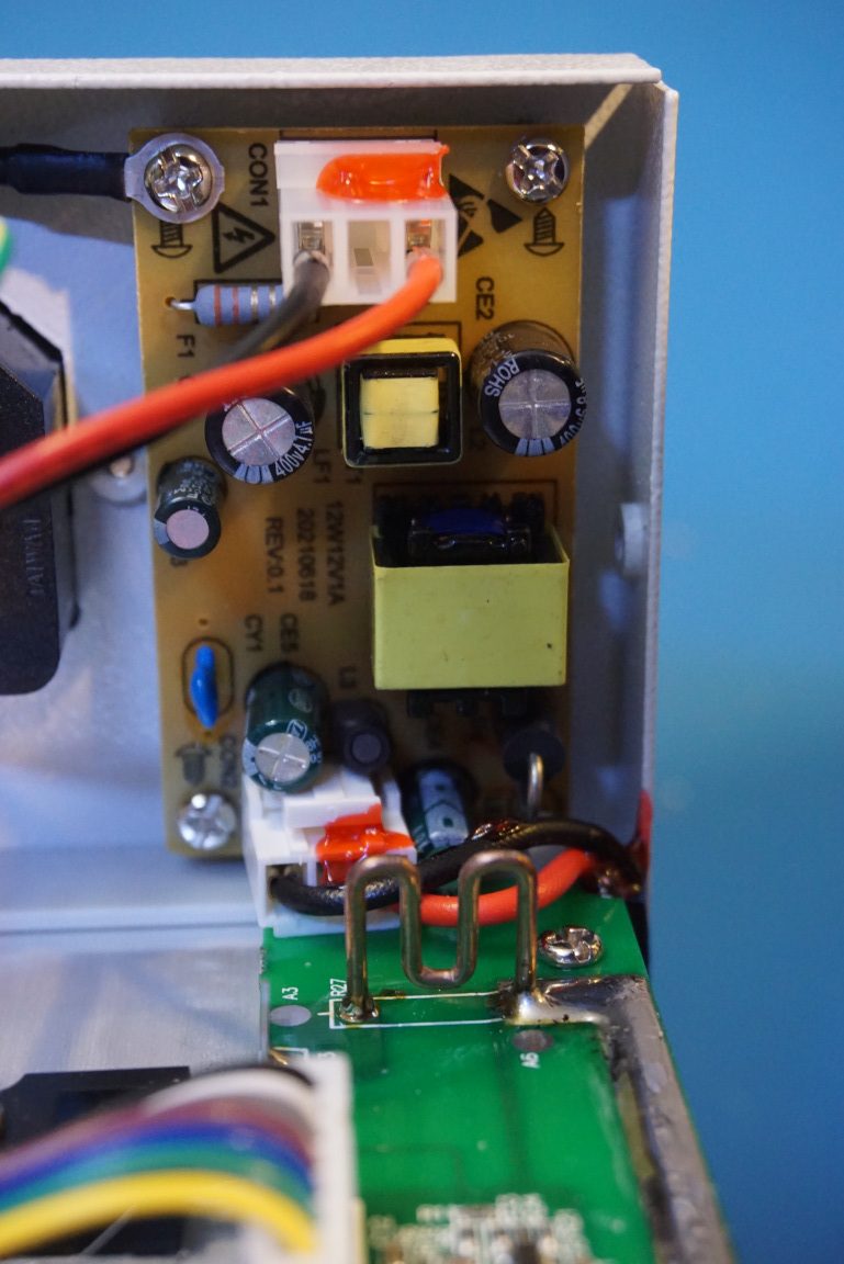
Here you can see the front panel PCB (to the left), and the main switching power supply board for the 12V that is used to power the ET5410+.
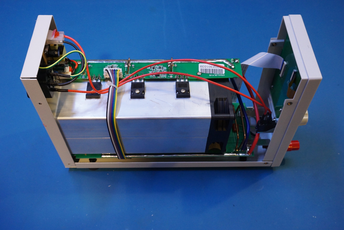
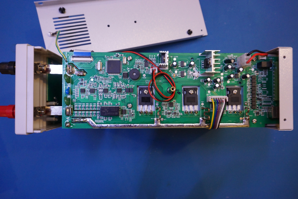
Here are a few pictures showing the electronic load with the bottom case cover removed. All the control circuitry is located on the bottom PCB and you can also see the additional three MOSFETS here.
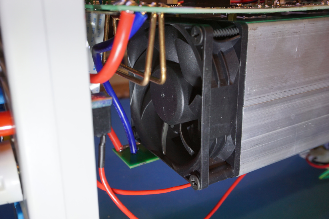
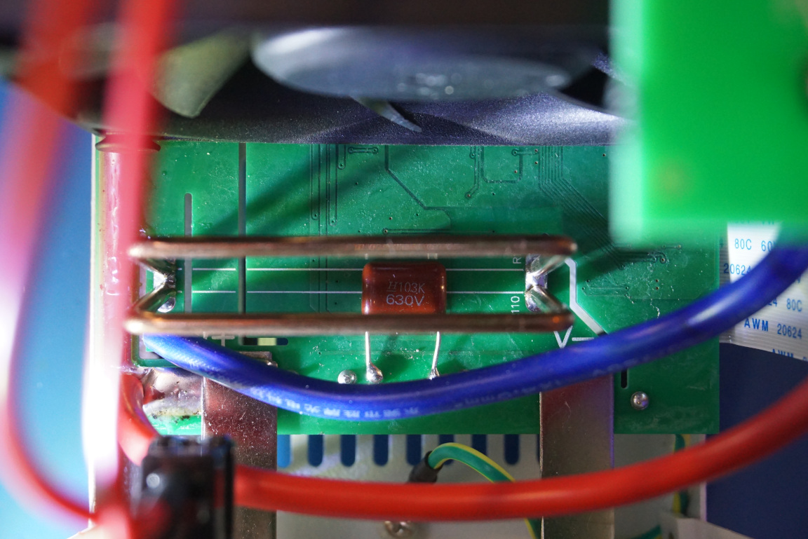
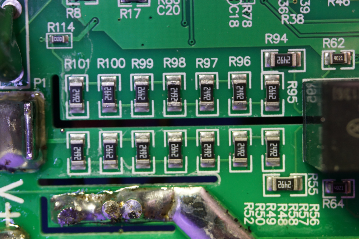
The picture to the left below shows a closeup view of the cooling fan. Air is blown through and along the length of the heat sink and the air comes out from the rear of the electronic load. Because of this design, the heat exchange is very efficient. In these pictures you can also see the main current shunt used. Because of the high current (up to 40A) flowing through, there are two shunts doubled up. The main current shunt is used for the sink current measurement.
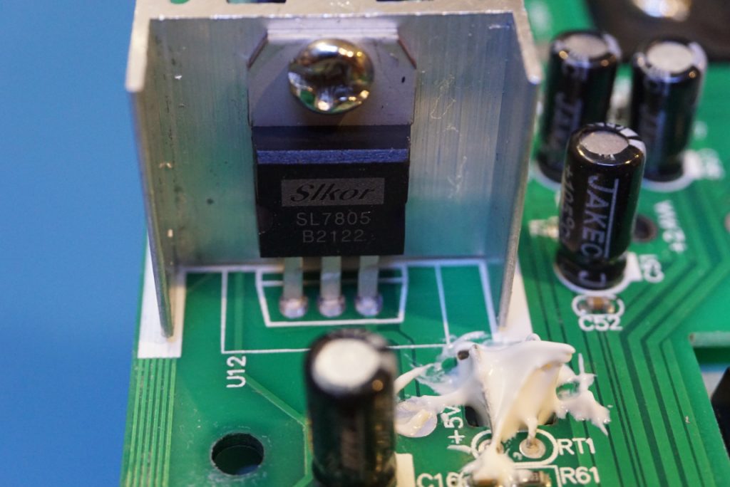
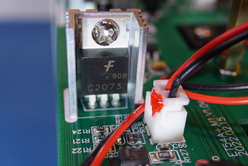
On the main PCB, there are quite a few linear regulators, below to the left is a picture of a 7805 5V regulartor. To the right, the 2SC2073 is a power transistor for the fan operation.
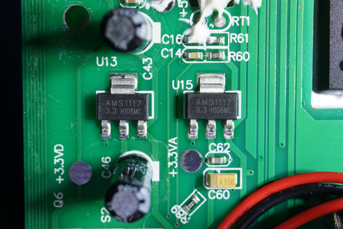
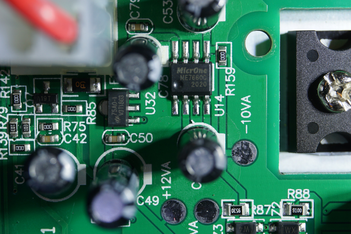
There are additional power rails. The 1117 provides the 3.3 V voltage and the ME7660C is a charge pump that generates both positive and negative rails for the OpAmps.
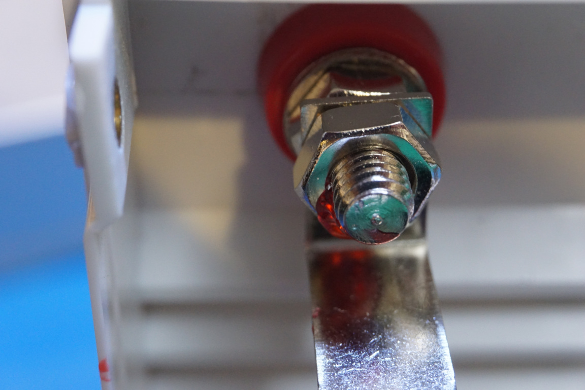
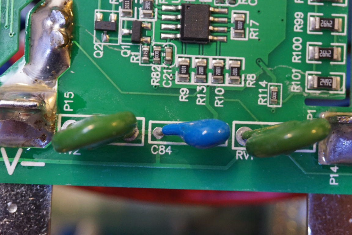
In the picture to the left below, you can see how the banana jacks are connected to the main PCB. The connection is quite beefy but the voltage sensing is done on the PCB rather than at the terminals so the voltage readback is a little bit off especially when the load current is high. Towards the right, you can see the input protection MOVs for transient suppression.
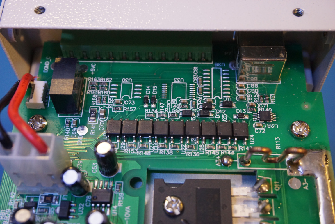
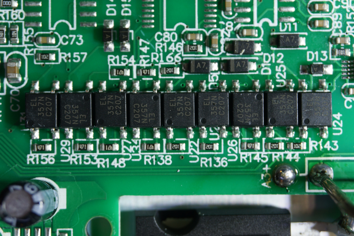
The picture to the left below shows the fan controller section. And the other two pictures show the protocol interface section towards the back of the electronic load. As mentioned earlier, this electronic load can communicate with PC and other devices via USB and other protocols. This section is properly isolated from the electronic load as you can see from the use of all those opto-isolators.
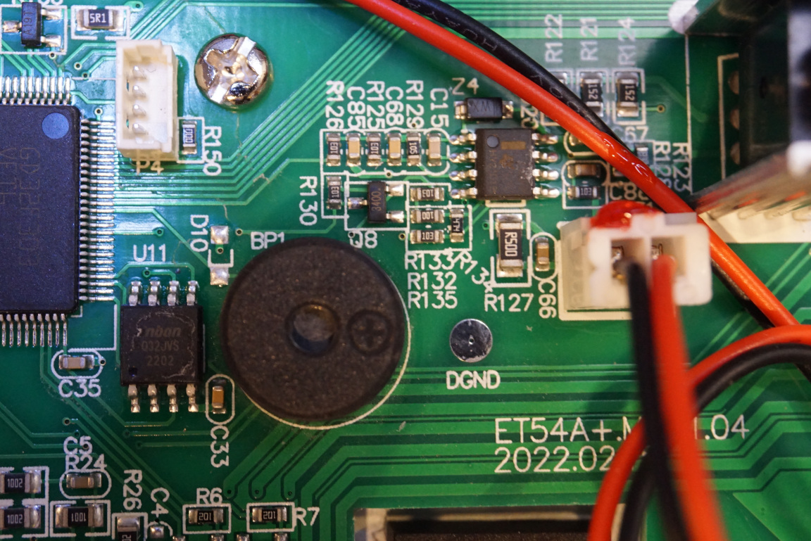
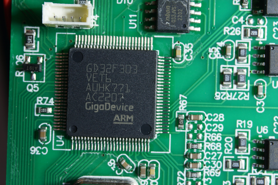
In the picture below, you can see that there are proper isolation slots physically separating all the high energy areas. The microcontroller used is the now ubiquitous ARM Cortex M4 MCU. It is a GigaDevice’s GD32F303.
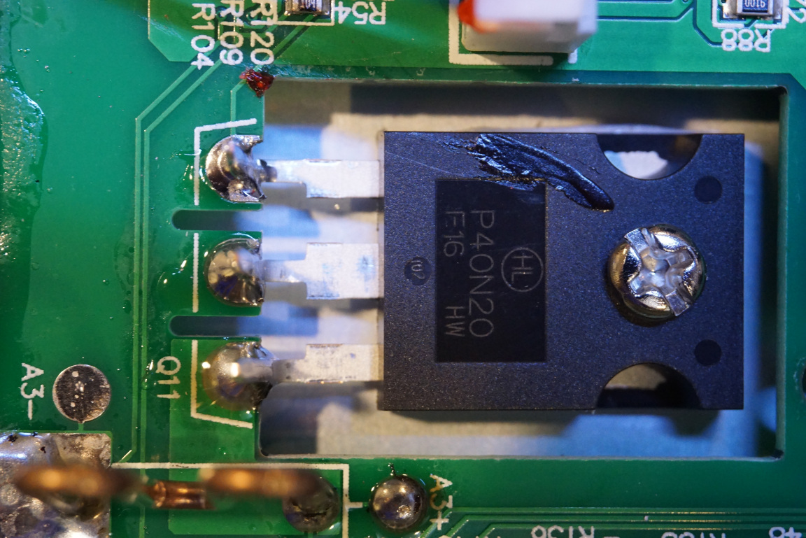
Finally, here are a couple of pictures showing the MOSFETs used. They are P40N20. The cutouts on the PCB allow these MOSFET to be mounted almost flush with the PCB and thus saving a lot of space.