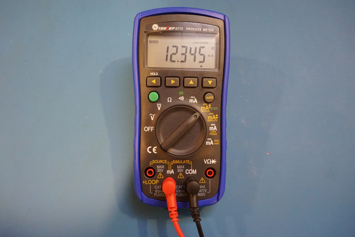
A process meter is mainly used in industrial settings and typically for loop calibrations. It can do basic DMM measurements and has many unique features such as the ability to source and sink current up to 20 mA. These features can come in hand in a lab setting outside the intended industrial use as well and make it a great tool to have even for hobbyists.
I recently received a ToolTop ET75 process meter and did a detailed review on it, for those who are interested in the review, you can check out the video below:
The ET75 has some of the functionalities of a standard DMM, for instance it supports DC voltage measurement up to 50V, AC voltage measurement up to 500V and can also measure resistance (up to 5k) and DC current (20 mA). Where the ET75 really shines is its current sourcing and sinking capability and when used as a current source or current sink it has a resolution of 0.001 mA with a current accuracy of 0.2%.
In this blog post, let’s take a look at some of the detailed teardown pictures.
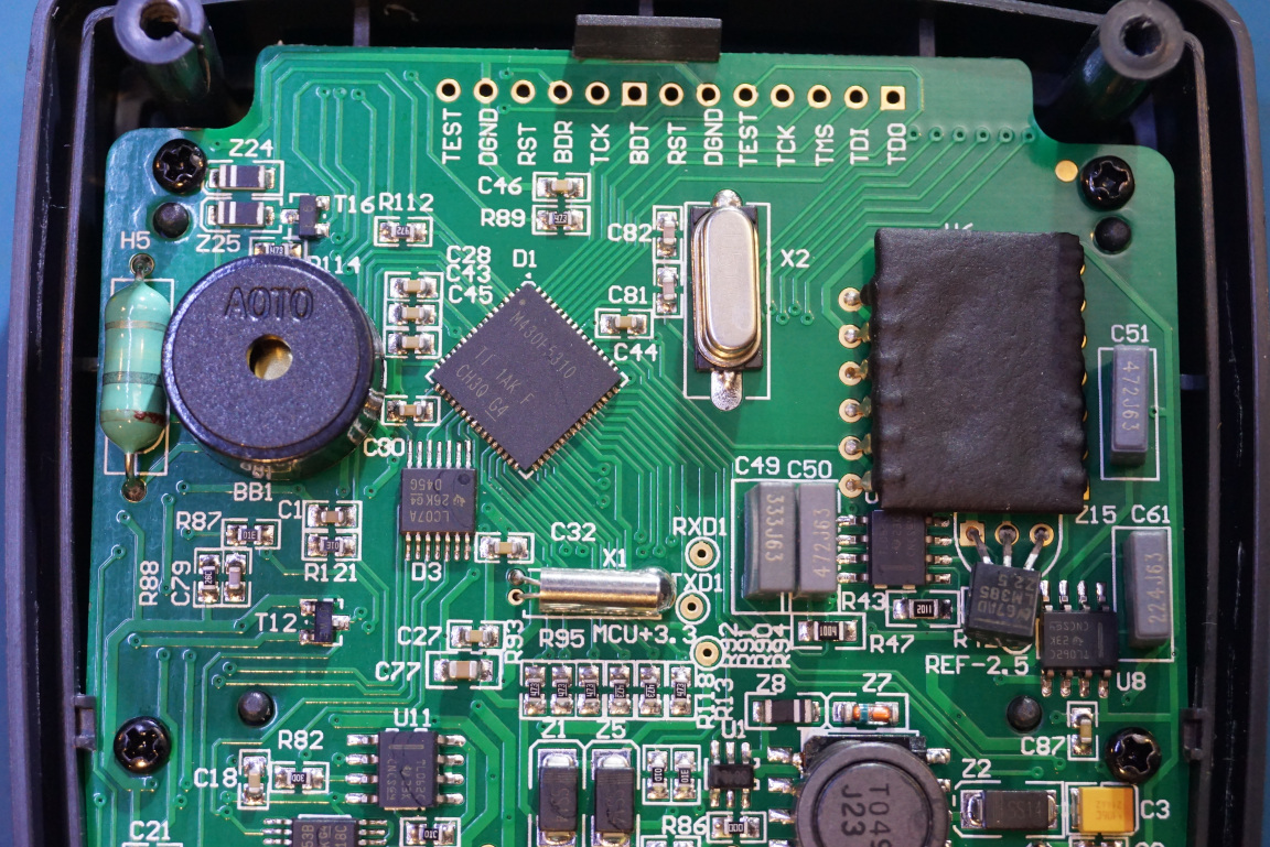
The overall layout of the components looks very clean. The meter is powered by two AA batteries.
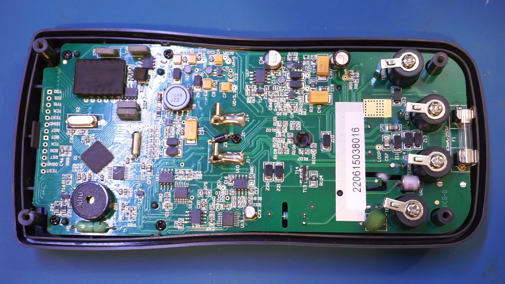
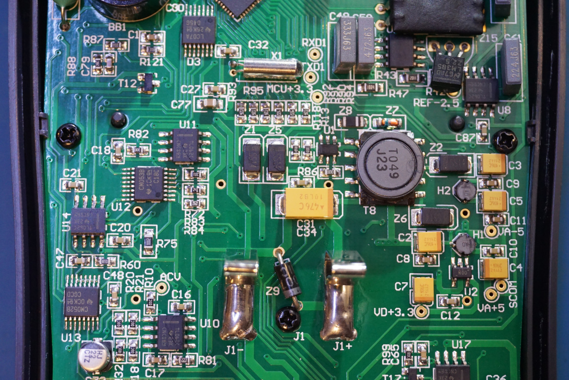
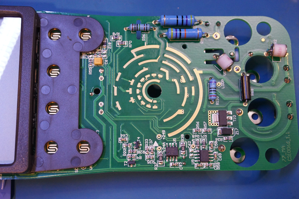
The MCU used in the ET75 is an MSP430F5310 mixed-signal microcontroller. In the picture to the right below you can see the inductor used for the onboard DC-DC converter which generates the 24V loop voltage. There are quite a few TL062 OpAmps used in this meter along with a few MUX switches (CM052B and CM053B).
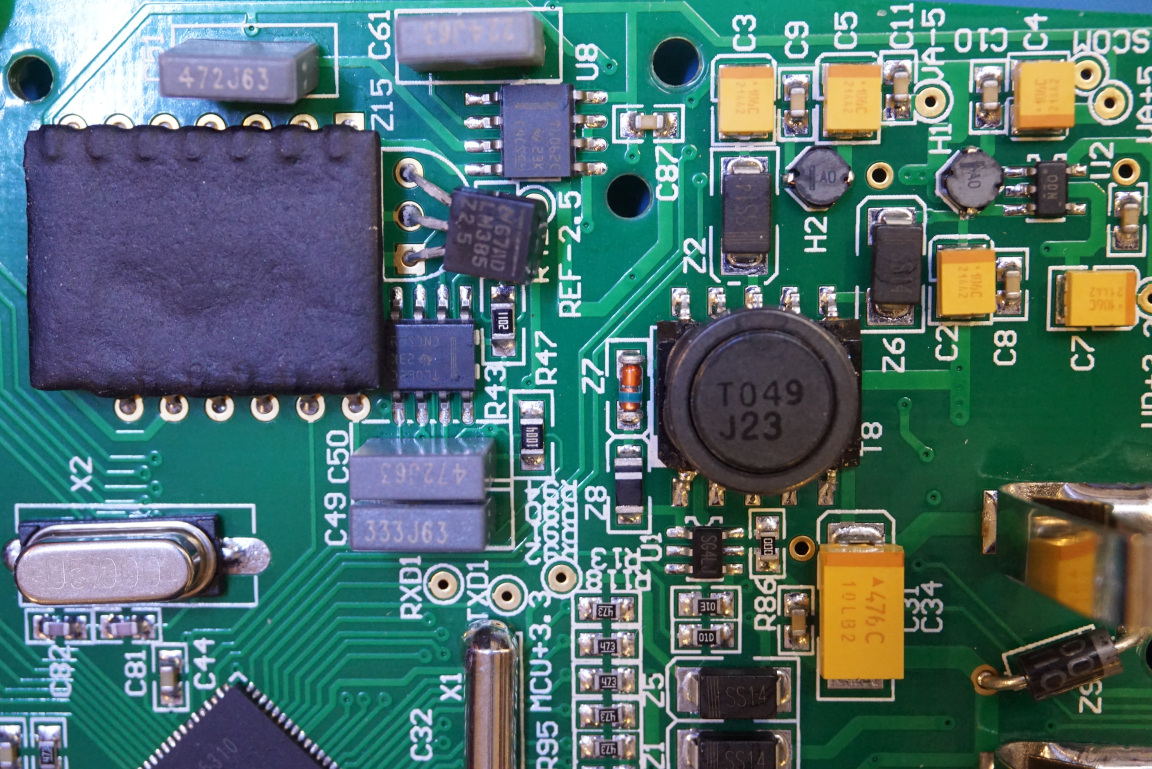
Here is a close up of the voltage reference section, the larger 14 pin device is presumably some kind of thick film device, some precision resistor network perhaps? The voltage reference used is a 2.5V LM385.
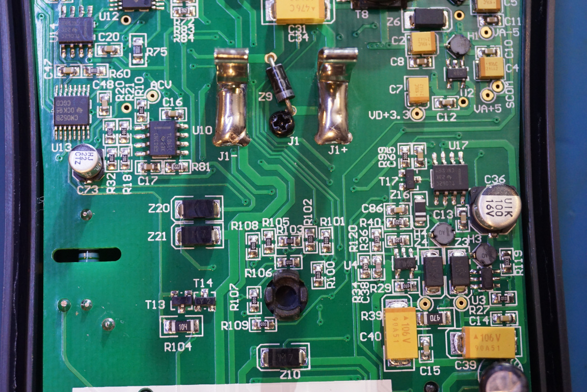
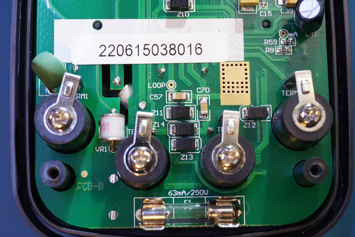
The picture to the left below shows the middle section of the PCB. Again there are a few more TL062 OpAmps. In the picture to the right below, you can see that unlike many of the cheap DMMs, there is adequate protection circuitry in place. There is one gas discharge tube on this side of board for voltage clamping. Two more on on the other side of the board (see picture later). There is also a PTC on the far left.
There are additional circuitry on the other side of the PCB as well.
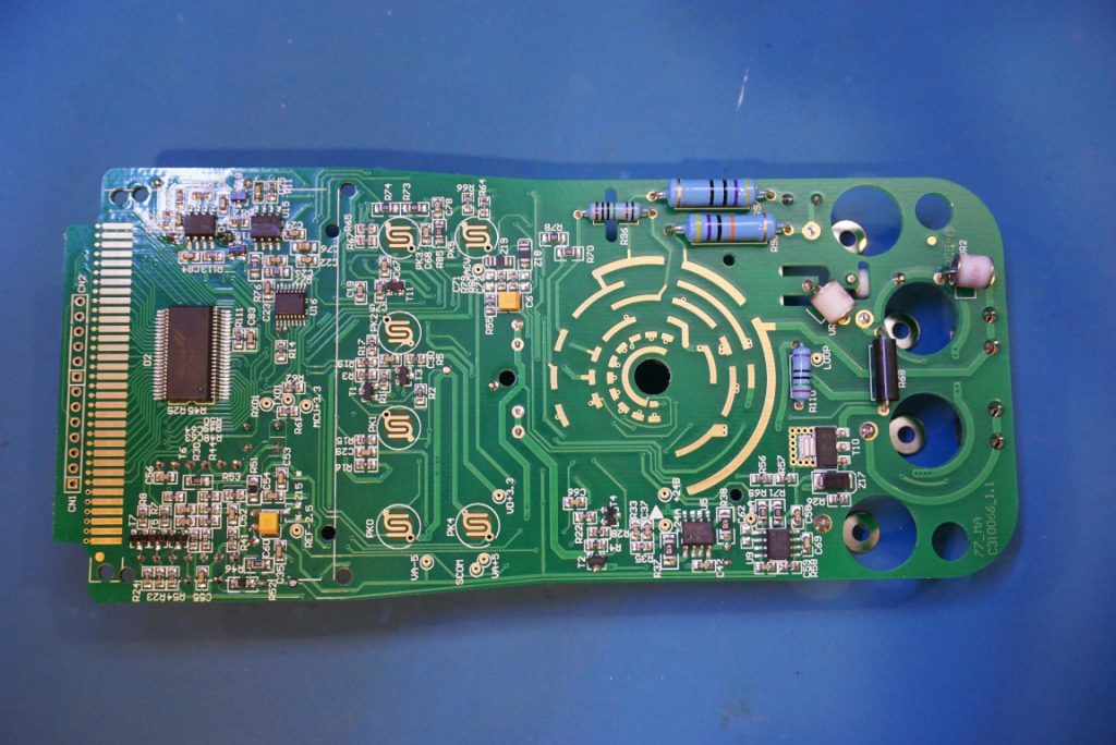
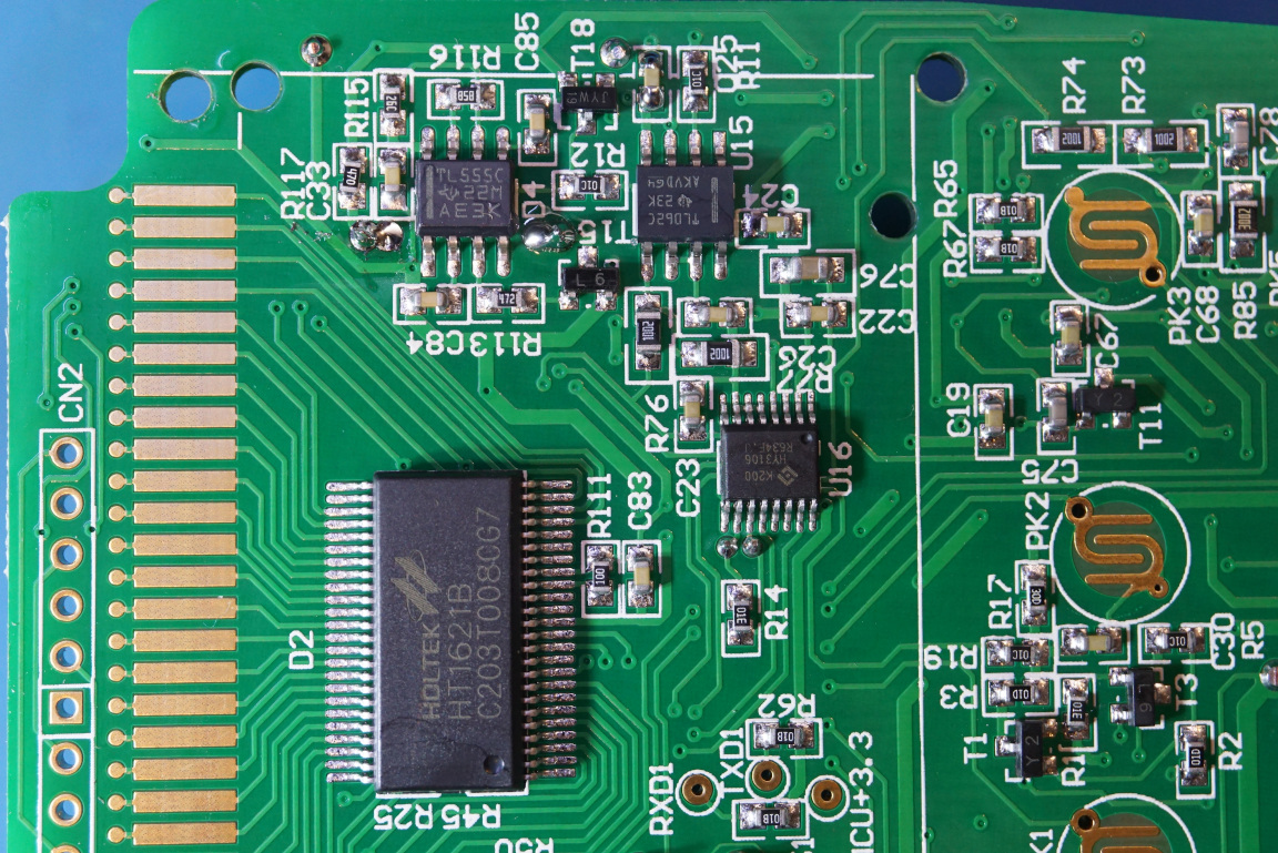
The LCD driver used is a Holtek HT1621B. To the right of the display driver there is an HY3106 24-bit ADC. Did you spot the venerable 555 timer?
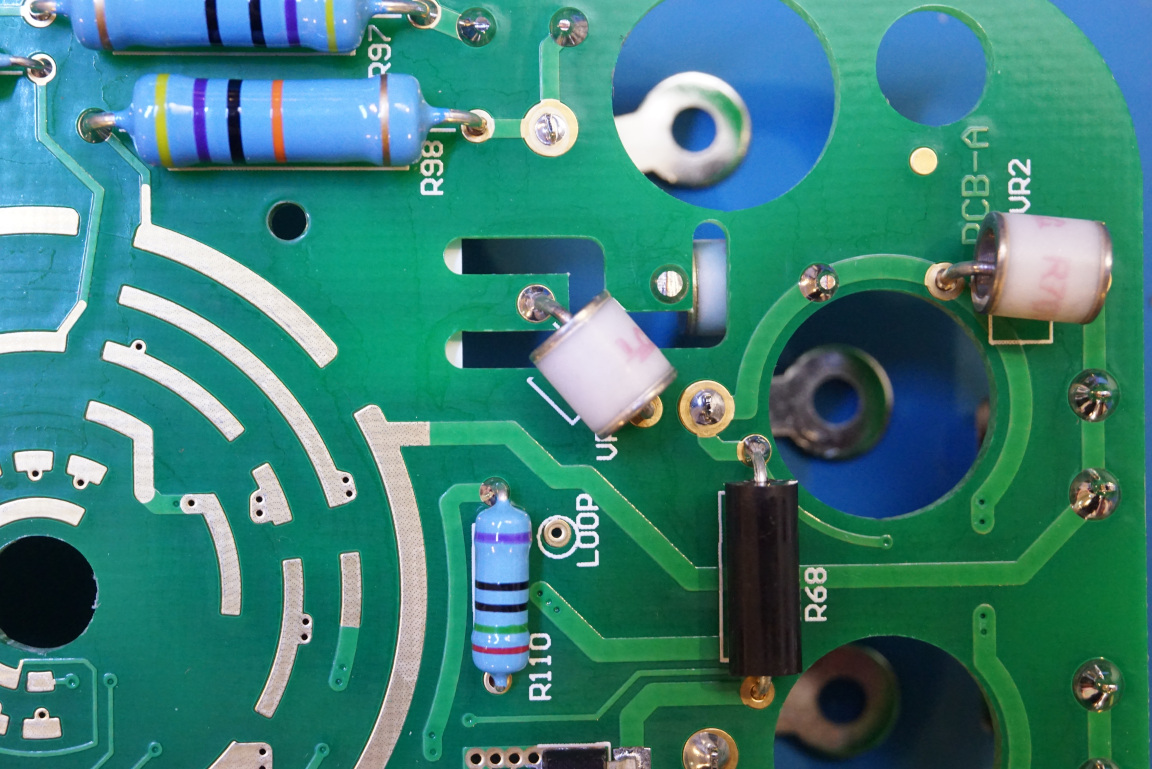
As mentioned earlier, there are two additional gas discharge tubes on this side of the board.
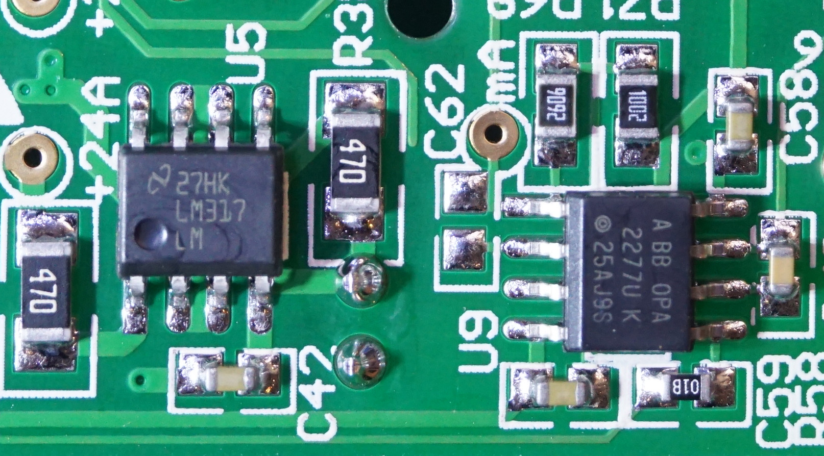
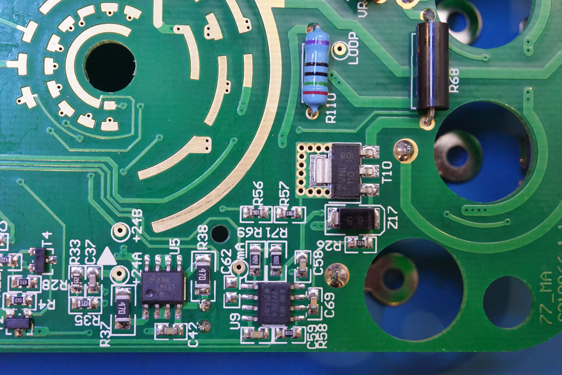
There is also an LM317 voltage regulator in the picture to the right, along with a 2277 high-precision low-noise OpAmp. The power MOSFET used is a ZVNL110, presumably for the current sink.