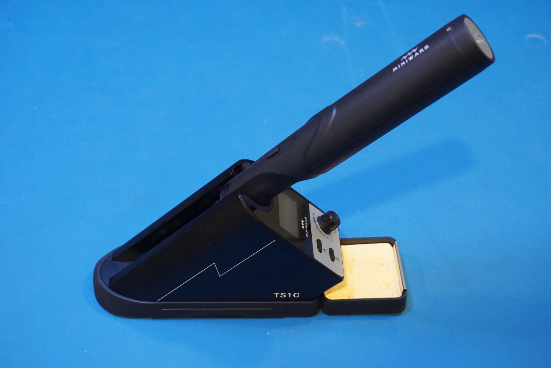
I did a review and teardown of a Miniware TS1C cordless soldering station. This soldering station is rather unique in that the soldering iron is powered by a supercapacitor instead of a traditional battery. While supercapacitors have limited capacities, they can be charged and discharged rapidly and have superior cycle life compared to rechargeable batteries. You can check out the review and teardown video below. In this blog post, let’s take a closer look at the internal constructions of the TS1C.
With TS1C’s design, the soldering iron communicates with the base station via Bluetooth. The temperature setting and display are both done at the base station side.
The picture to the left below shows the board inside the base station. The antenna used for the Bluetooth communication can be seen to the right. I was expecting to see a PCB patch antenna but I guess there is enough space inside the case for a physical antenna.
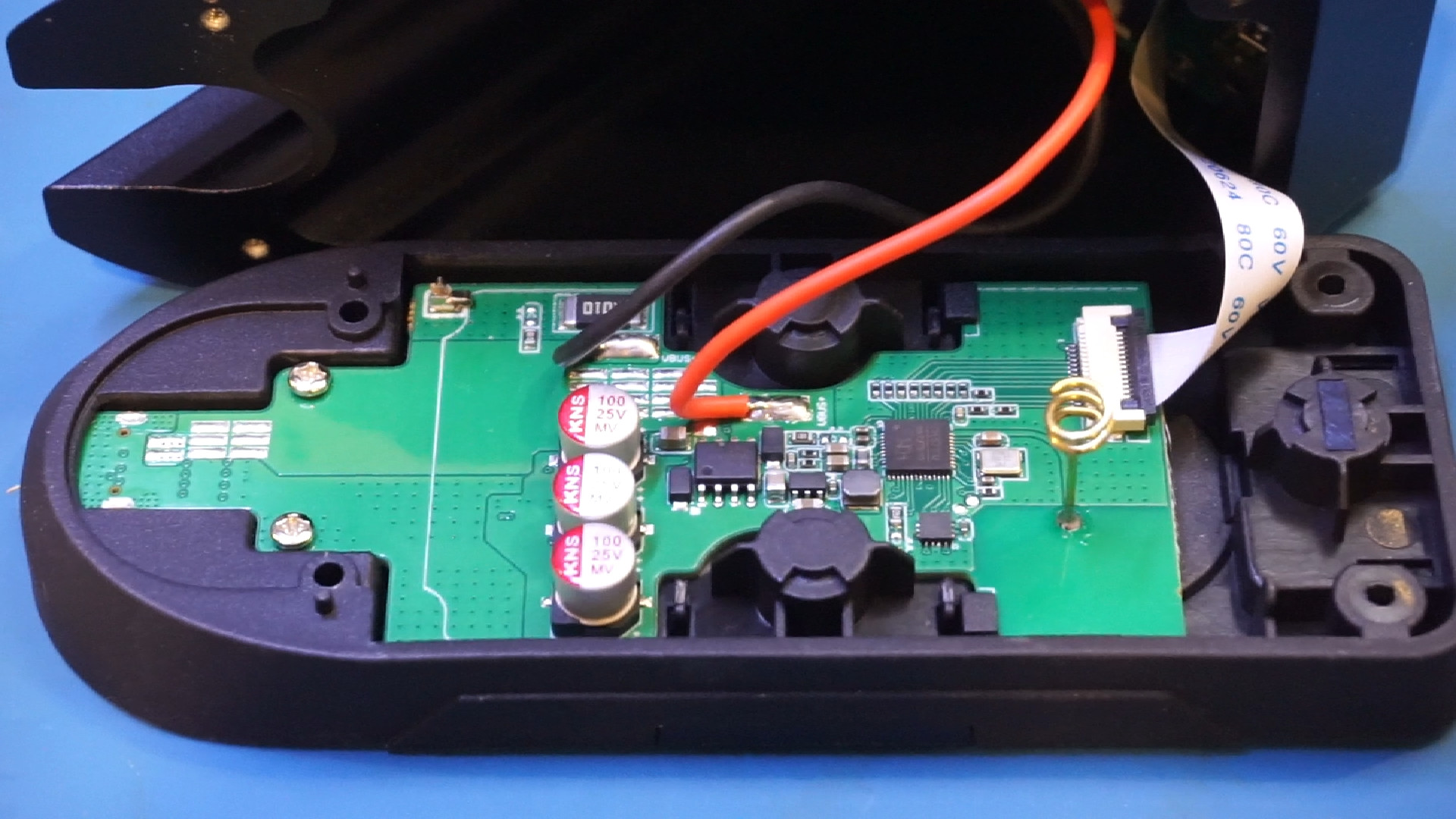
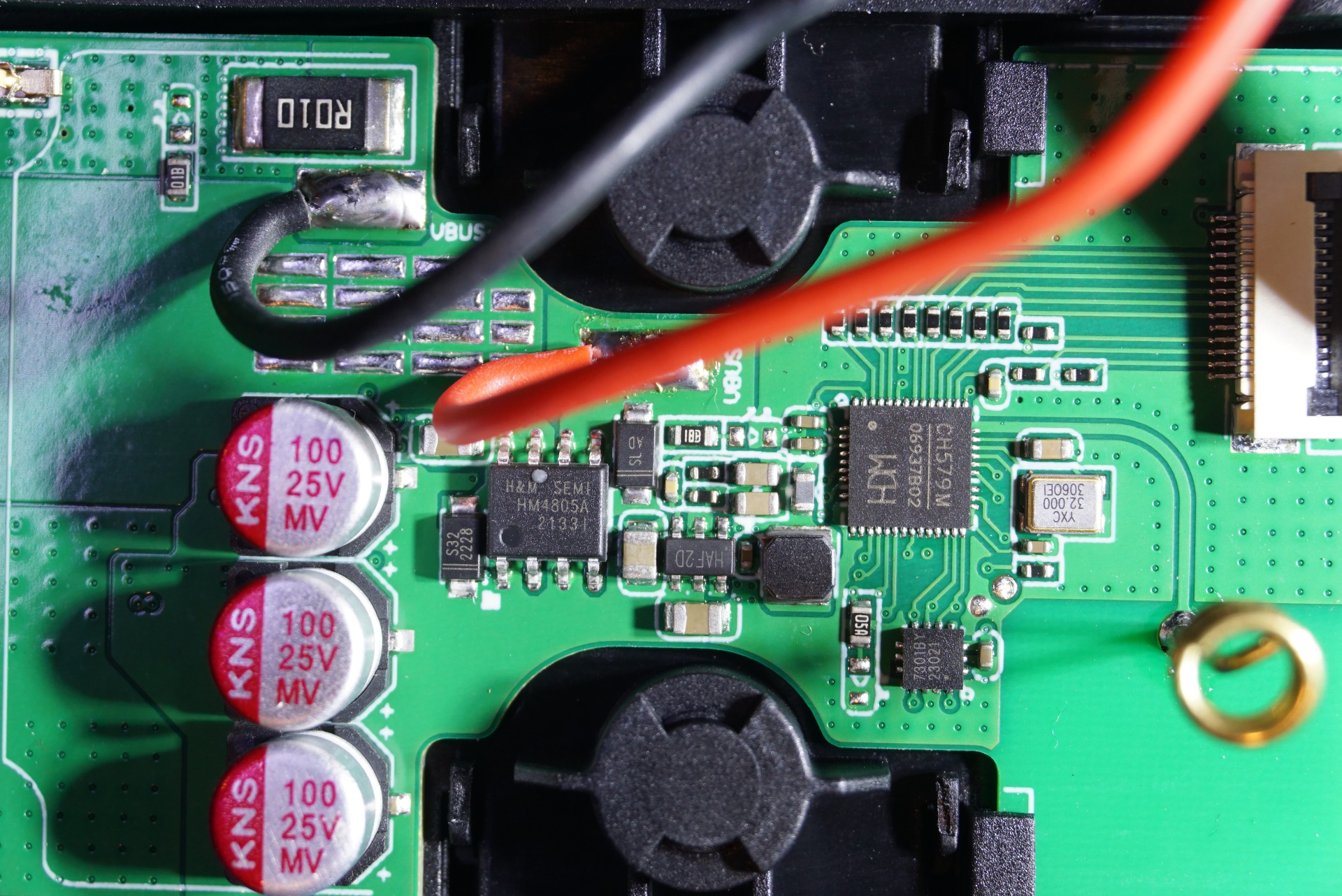
The main MCU used is a CH579M, it is has an ARM Cortex-M0 core and supports both ZigBee and Bluetooth communications. The 8 pin SOIC is an HM4805A which is a dual P-channel MOSFET which presumably is for switching the output for charging the hand piece. By the look of it, there is also a DC-DC converter section in the middle.
There is a separate PCB (not shown) inside the base that handles the input and the OLED display.
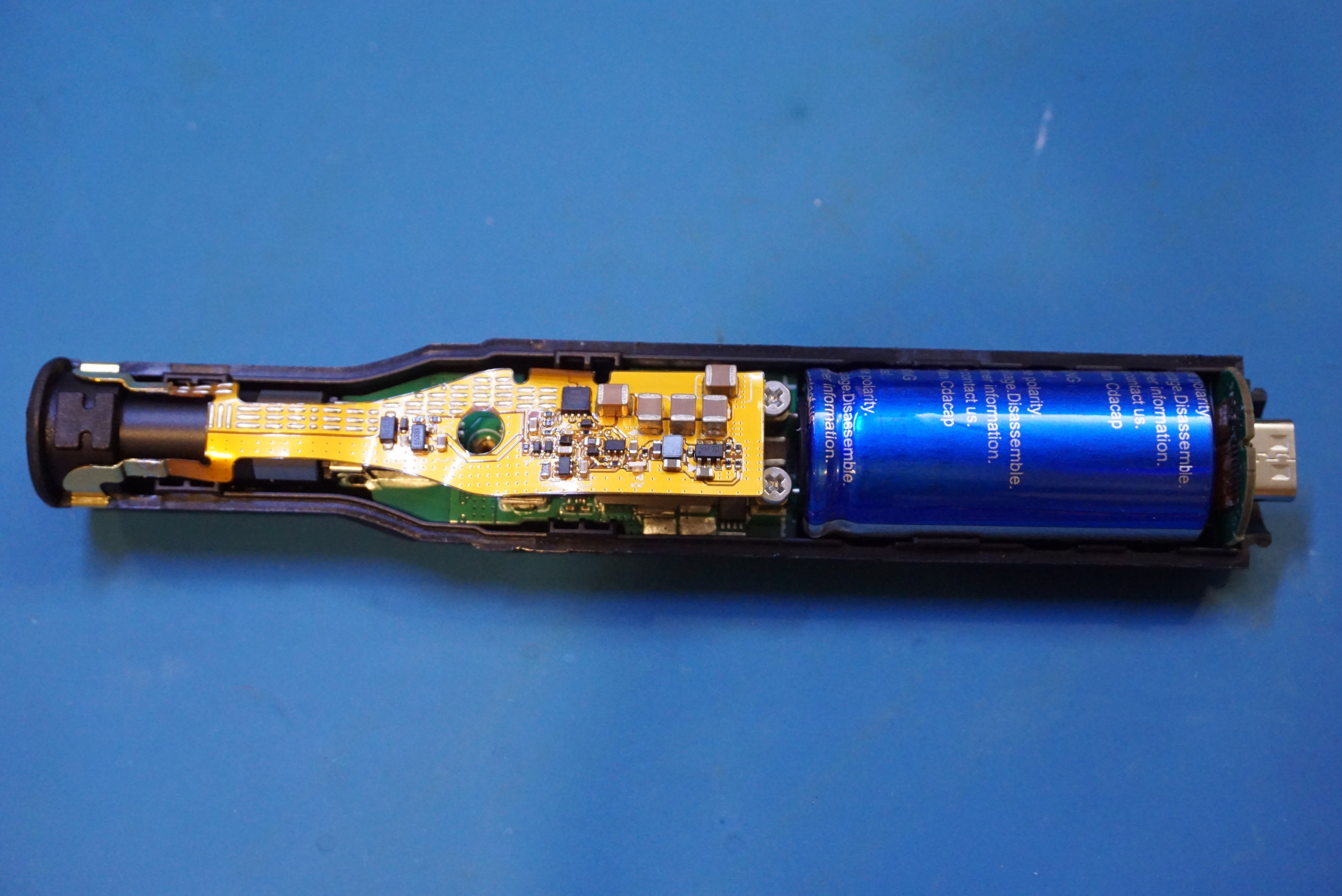
Inside the hand piece, there are essentially three PCBs. The center PCB that drives the iron element is a standard PCB and it is sandwiched by two semi-flexible PCBs.
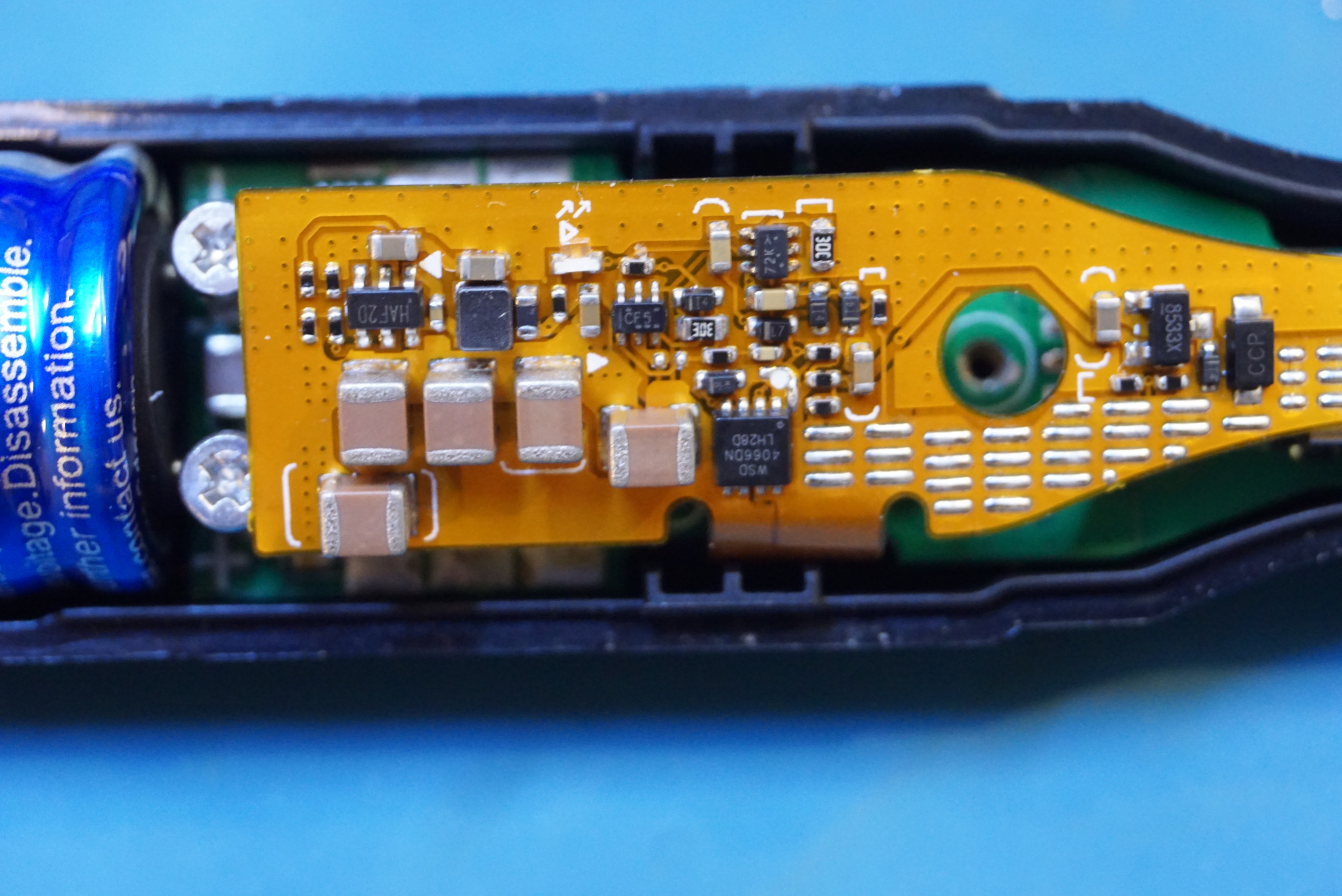
The picture to the left below shows the top PCB. This PCB is likely used to control the charging of the supercapacitor as it is connected to the exposed power input pads. The 8 pin SMD component marked 4066DN is a WSD4066DN dual N-channel MOSFET chip.
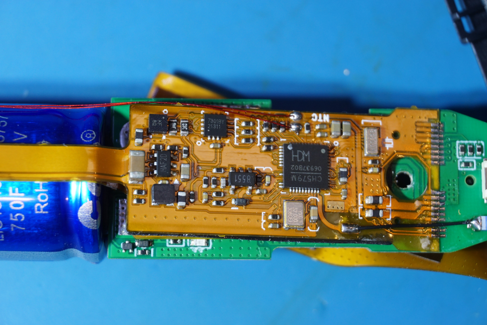
The picture to the right blow is the PCB at the bottom side. It contains the same CH579M. Besides controlling the soldering iron it is also used for Bluetooth communication with the base station. Again, instead of a PCB patch antenna the antenna used is just a thin wire with an inductor at the end.
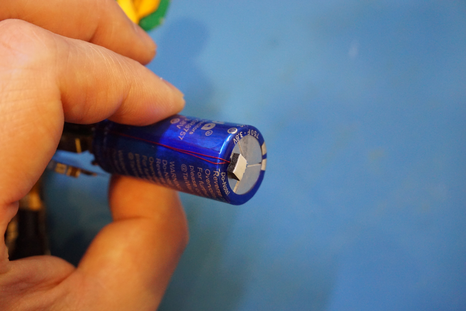
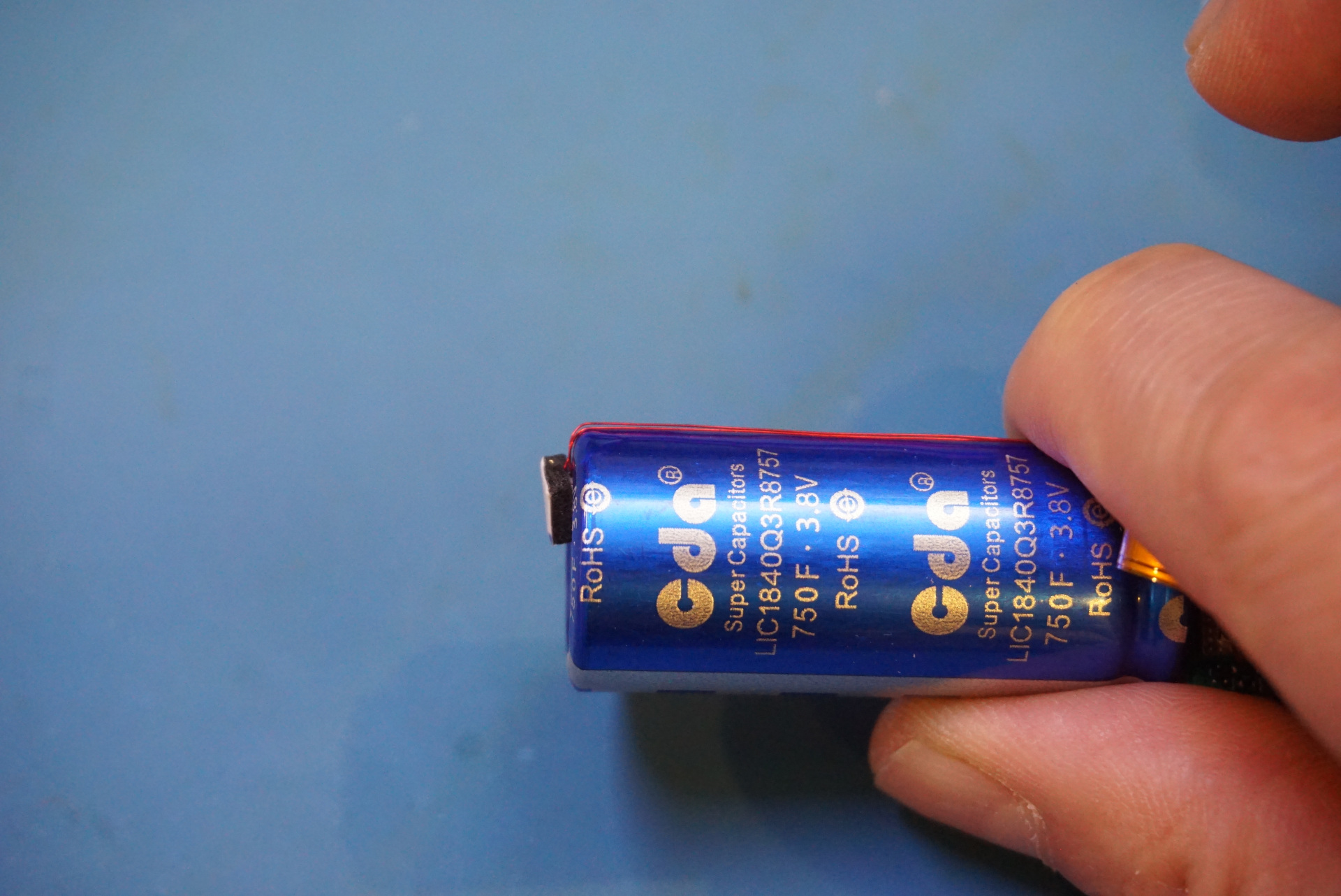
Finally, here are a couple of pictures of the supercapacitor used. It is a CDA 3.8V 750F supercap. There is an NTC on top of the capacitor for overheating detection.