Transistors operating in their avalanche regions are often used to generate fast rise pulses (see avalanche pulse generator using 2N3904). Many transistors can also avalanche when the connections to collector and emitter are reversed. When operating in reverse avalanche region, these transistors are sometimes referred to as negistors.
Because the asymmetry and doping differences between the base-emitter and base-collector junctions, the avalanche voltages for reversely connected BTJs are usually magnitudes lower than their normal avalanche voltages. Here, I decided to test a few different transistors and see at what voltages the reverse avalanche occur.
The circuit I used is a simple LED flasher, similar to what was described here. As with any circuit that exhibits negative differential resistance, the principle of operation is quite simple. The capacitor is charged via a current limiting resistor. When the voltage is low, the current that flows between the emitter and collector is roughly the reverse current of a diode which is negligible. When the voltage across the capacitor reaches a certain level, the transistor enters the avalanche breakdown mode. In its avalanche breakdown region, the transistor exhibits negative resistance (i.e. the higher the current, the lower the resistance) so the capacitor discharges rapidly through the LED and the voltage across drops until the avalanche mode can no longer be sustained. At such point, the transistor enters its normal operation mode and becomes non-conductive again. Thus the cycle continues. The rapid discharging through the LED manifests itself as short blinks. The blinking frequency largely depends upon the RC constant and the transistor breakdown characteristics.
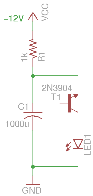
Depending on the LED you use, you may need to add a current limiting resistor to protect the LED during discharge. But for a typical 5mm white LED, no resistor is needed as the duration of the current flow is extremely short.
Using the RC values in the schematic above, I measured the minimum voltages required for the circuit to oscillate using different transistors and the results are listed below:
| 2N4401 | ~12.5V |
| SS9014 | ~12.5V |
| 2N4124 | ~12V |
| 2N3904 | ~12V |
| BD137 | ~11V |
| BD139 | ~11V |
| BC337 | ~9V |
| SS9018 | ~8.2V |
At first glance, we can see that many transistors can be used to make this simple flasher. And for the majority the minimum voltage required is at just around 12V. SS9018, a high frequency NPN transistor, is a noticeable exception. It can oscillate at a voltage as low as 8V, which means it can be simply powered by a 9V battery. The threshold voltage for BC337 is only a tad higher at 9V.
Another interesting thing I noticed is that the same transistor from different manufacturers or even different batches can behave quite differently. For instance, while I could get one batch of 9014’s to oscillate at around 12 to 13 volts consistently, the 9014’s from another batch would not oscillate at all. So your results might be quite different than what I have here.
Also, while I could get most NPN transistors to oscillate in their reverse breakdown regions I could only get a couple of BD138 PNP transistors to oscillate using the same circuit above (power polarity is reversed). And the oscillation only occurred at a very tight voltage interval (e.g. ±0.05V).
One of the useful features of a standard avalanche pulser (like this one) is its extremely fast rise time (sub nano second), so can we use negistors to build similar pulsers?
Well, the short answer is no. After some experiments it appeared that the rise time of a negistor pulser is magnitudes higher (e.g. ~100ns) than a typical avalanche pulser.
The circuit below shows my experiment setup:
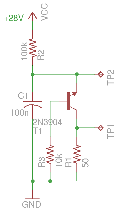
One of the key differences in this circuit between a negistor pulser a standard avalanche pulser is that the capacitance cannot be arbitrarily small. In my case, 100nF seems to be near the lower limit. Also notice the based resistor (10K) used to reverse bias the base-collector junction. Like in standard avalanche pulser the inclusion of the base resistor increases the avalanche breakdown threshold voltage which translates into higher avalanche current and shorter rise time.
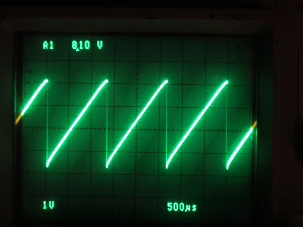
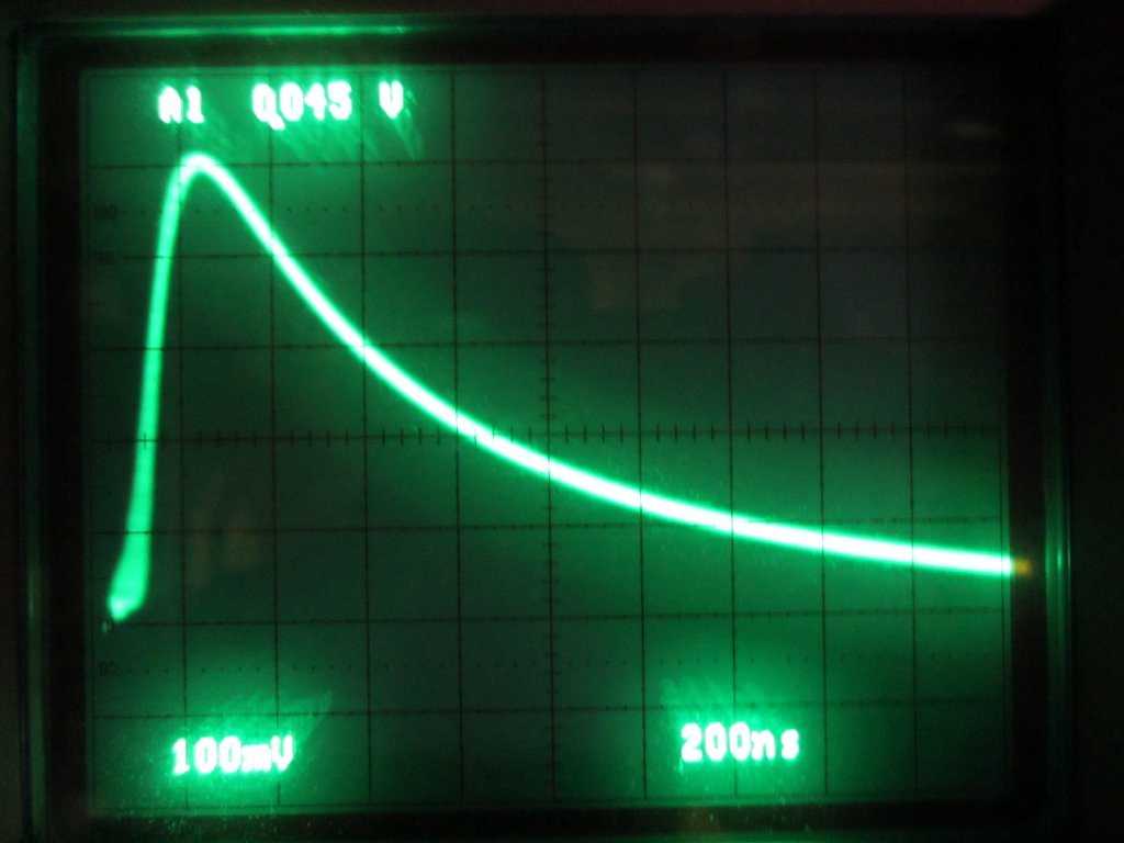
The oscilloscope capture below shows the waveform measured at the collector (TP1). The pulses are repeated at roughly 500Hz when the supply voltage is around 28V.
Here is a single pulse viewed at a much smaller time base. As you can see, the rise time is no where close to the nano-second rise time we get using the standard configuration, but at under 100ns the rise time is still pretty fast.
Because these narrow pulses have extremely wide frequency spectrum, you can easily pickup the 500Hz audio signal using an AM or shortwave radio over the entire frequency range. The wide frequency spectrum serves as the carrier frequency and the pulse intervals becomes the audible signal. And the negistor pulser shown above can operate over a wide range of supply voltages, from around 20V upto more than 100 volts. As the voltage changes, the pulse interval changes as well and if you have a radio close by, you can hear the audible tone ramping up and down as you adjust the supply voltage.
The waveform at the emitter (TP2) illustrates the charge and discharge of the capacitor. Since the capacitor is only charged briefly to a fraction of the supply voltage before avalanche breakdown occurs, the linearity of the sawtooth signal is quite excellent.