In my previous video featured on EEVBlog I did a teardown of an HP 493A microwave amplifier along with the traveling wave tube inside. I actually had done a teardown of an identical unit a while ago but this time I managed to take a peek at the traveling wave tube inside.
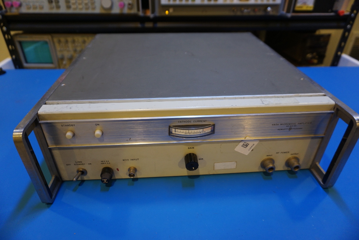
This unit looks slightly older than the one I did a teardown with back in 2014 and is missing a couple of components in the high voltage section so it no longer work. Generally I hate to do any destructive teardowns, but the traveling wave tube inside this unit has long passed its prime time (I tested it by swapping the traveling wave tube with my working unit and it turned out to be very weak) so I thought it would be a great opportunity to take a look at its construction.
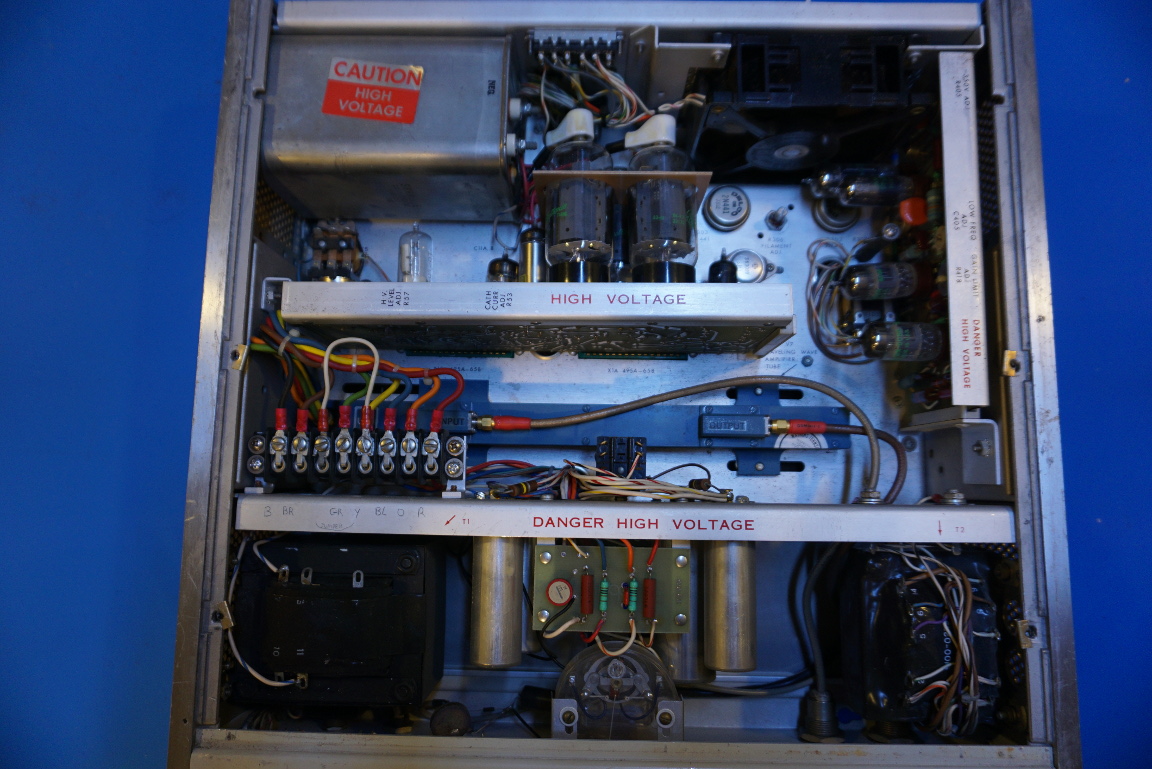
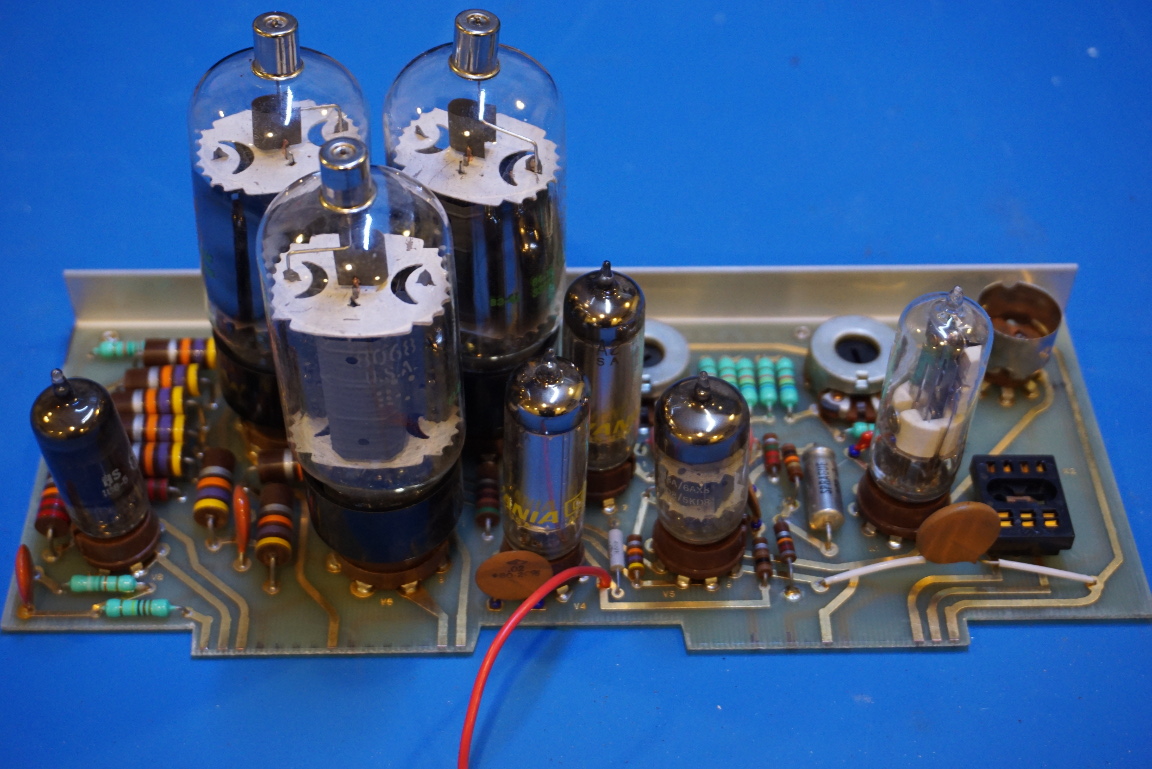
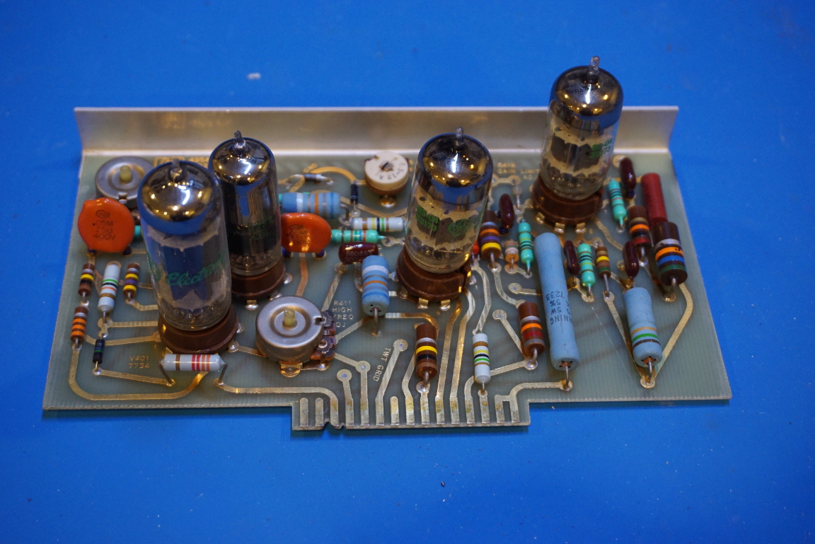
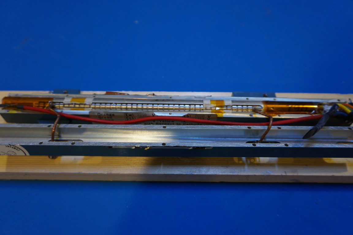
The main active circuitry inside this TWT amplifier is a high voltage regulator board (on the left) for the traveling wave tube and a modulation board (to the right) if a modulated output signal is desired. At the heart of the high voltage regulator board are three 8068 beam pentode tubes.
|
|
A few germanium power transistors were also used in the regulator circuitry for the filament power supply.
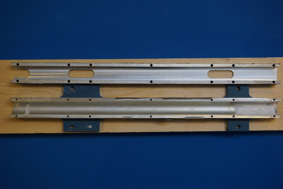
The traveling wave tube itself is housed in a meticulously machined enclosure (presumably aluminum). A metal casing is necessary to ensure environmental electromagnetic field does not interfere with the operation of the tube as TWT utilizes magnetic field along its axis to constrain the electron beam within the helix. Without getting into too much technical detail, it is sufficient to say that signal amplification is achieved via the interaction between the electron beam and the electromagnetic field induced via the traveling wave within the helix. When the traveling speed of the electron beam approximates that of the field moving through the slow wave structure (the helix), energy exchange happens between the electron beam and the RF field and thus amplification occurs. If you are interested in the details, you can check out the book “Principles of Electron Tubes” by J. W. Gewartowski and H. A. Watson.
|
|
In the two pictures below, you can see the input and output rigid coax coupling. For some reason, the rigid coax looked deformed. Usually it is important to use special tools to bend rigid coax cable as any changes in its dimension affects its RF characteristics. I am not entirely sure why there are many kinks in them.
|
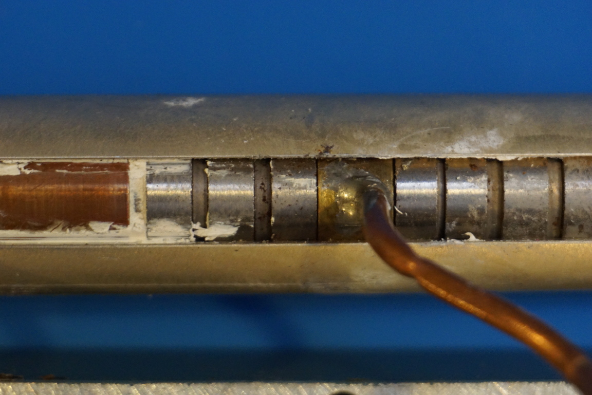 |
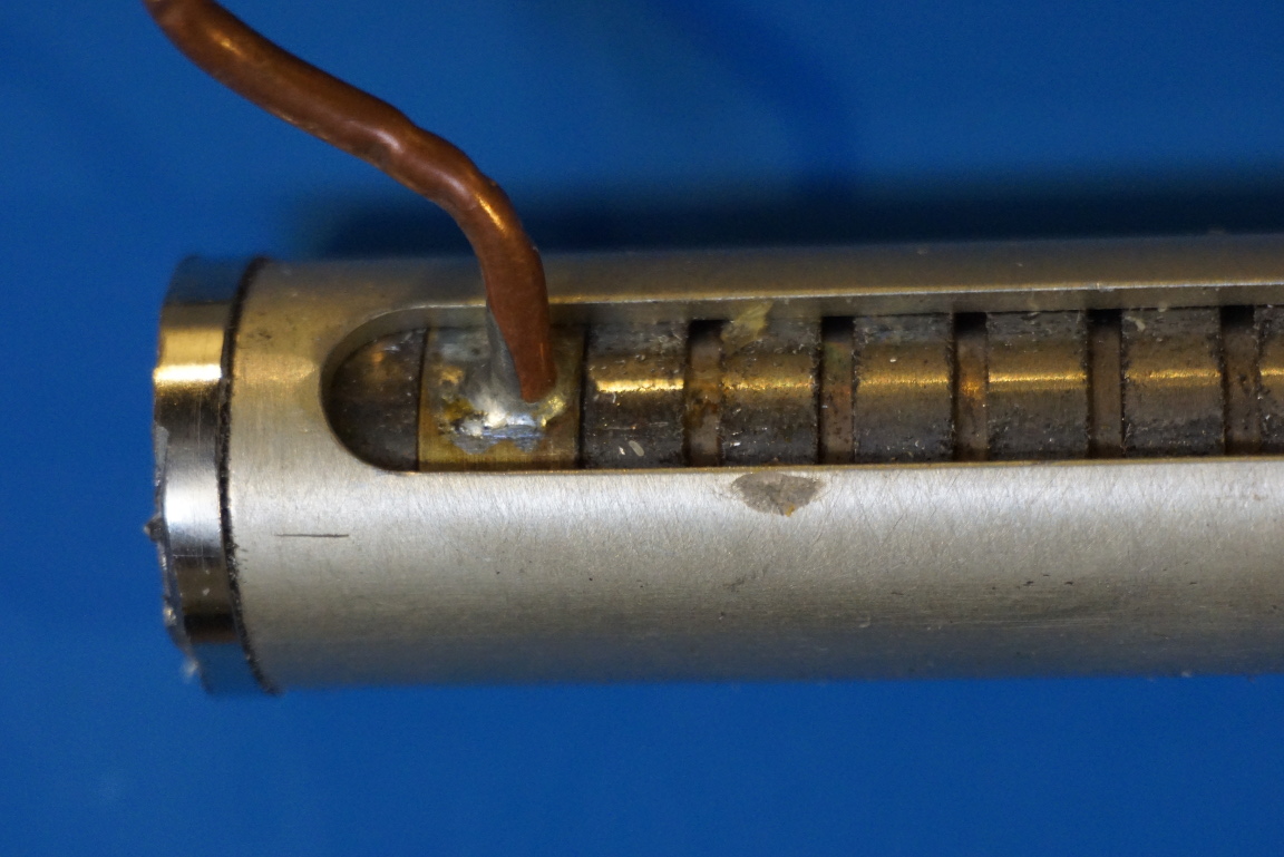
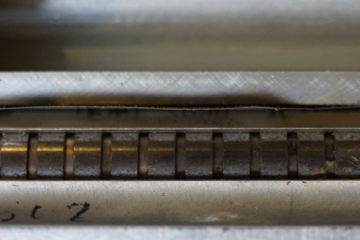
As mentioned earlier, the electron beam inside the tube is focused and constrained via the magnetic field generated by the ring magnets along the length of the tube (see picture below). One interesting thing is that the manual mentioned specifically that the tube needs to be sufficiently cooled during normal operation and the magnet could loose its magnetism should the temperature rises too high. This fact indicates a relatively low Curie temperature of the magnetic material used. Perhaps some sort of rare earth material?
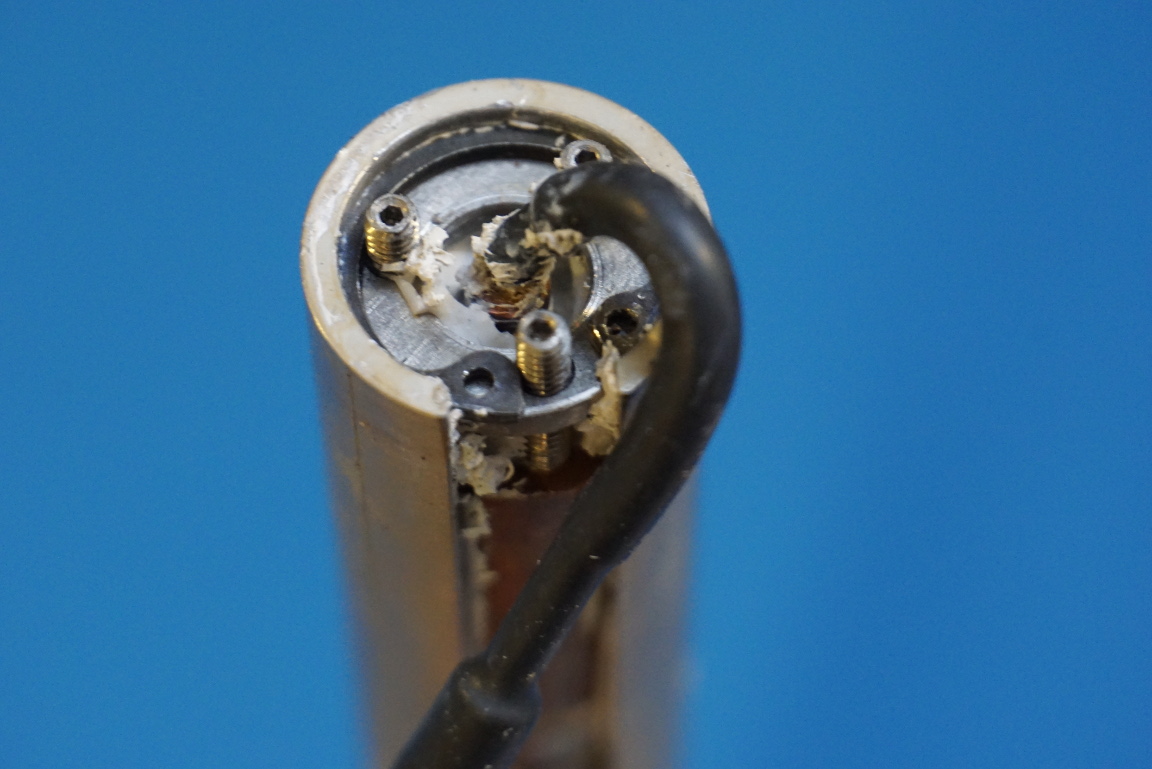
This picture shows the anode/collector side of the tube.
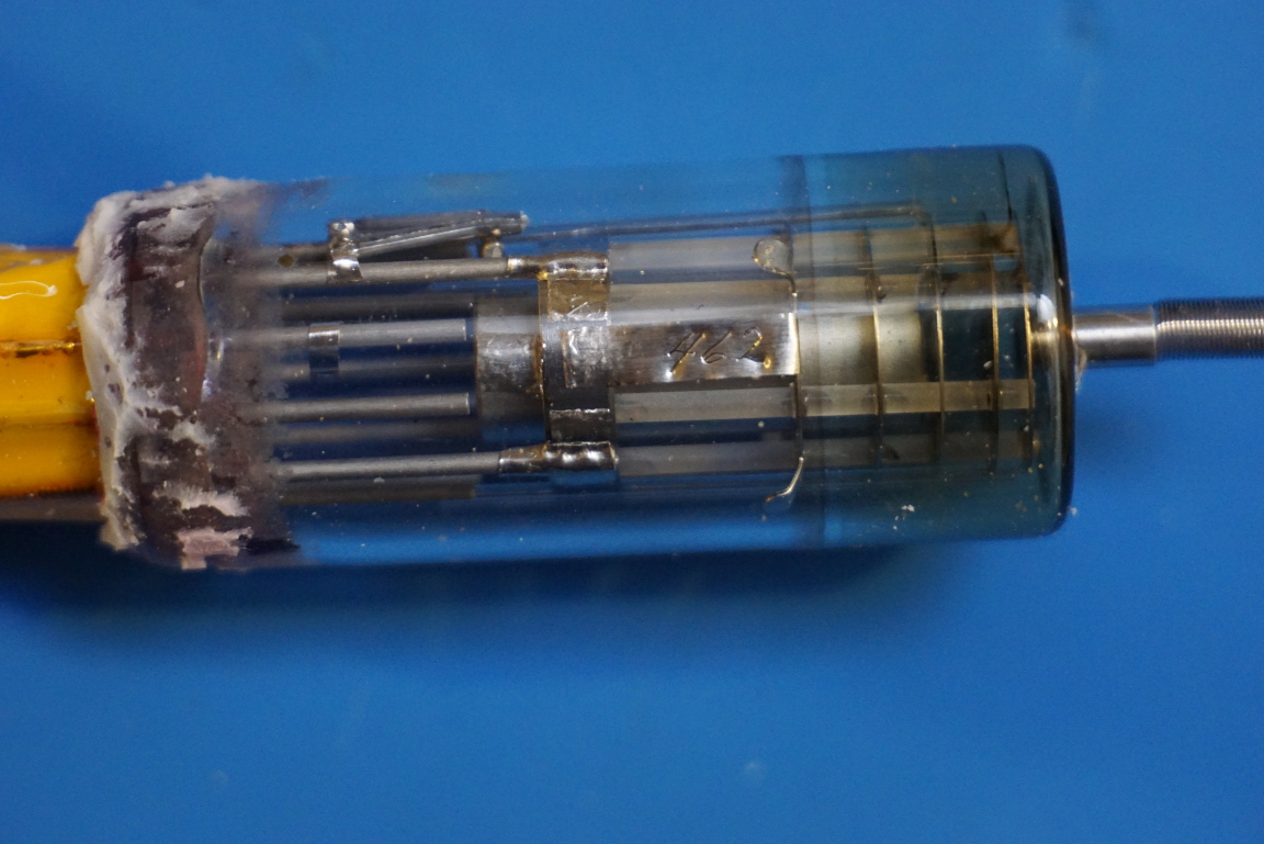
While trying to remove some of the silicone sealant from the tube, I accidentally broke off the electron gun portion of the tube. Not sure if this could have been avoided with more care as the section that houses the helix is very thin and fragile. But in a way I was glad this portion broke off as we could at least see it close up. It looks very similar to the electron gun of a cathode ray tube (CRT) and this should not be a surprise as they more or less are doing the same job. In the picture below you can also see the helix coming out from the electron gun.
If you look carefully, the tip of the glass envelope looks darker than the rest of the glass body. At first I thought that this was due to the deposition of the cathode materiel through use. But a closer look suggests that the top was made of a slightly different material as you can see a clean line dividing the tinted portion and the clear portion.
As it turned out, this is likely uranium glass. Using a 405nm laser, you can clearly see the uranium oxide fluoresce, giving out beautiful green light. The uranium glass is only slightly radioactive however. My Geiger counter gives a 20 µSv reading which is only ever so slightly above the background radiation level of around 10 µSv in the lab.
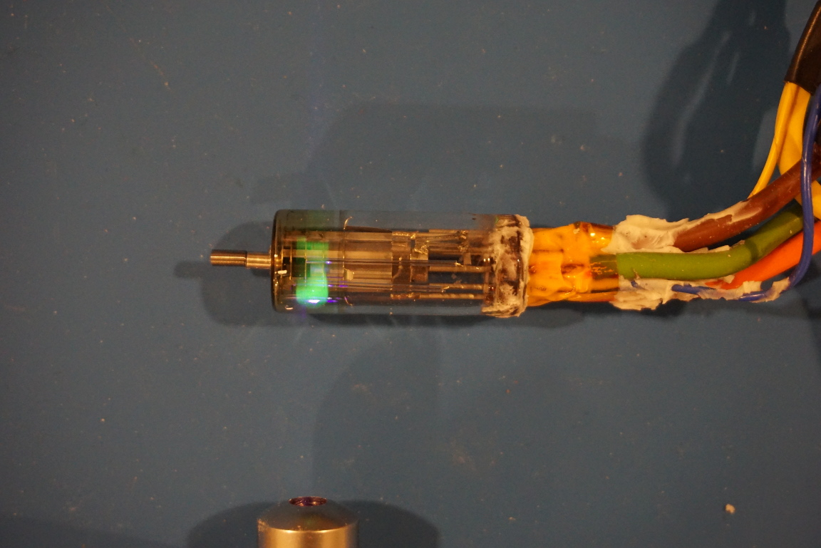
Here is a short video showing the radioactivity of electron gun portion of the TWT.

