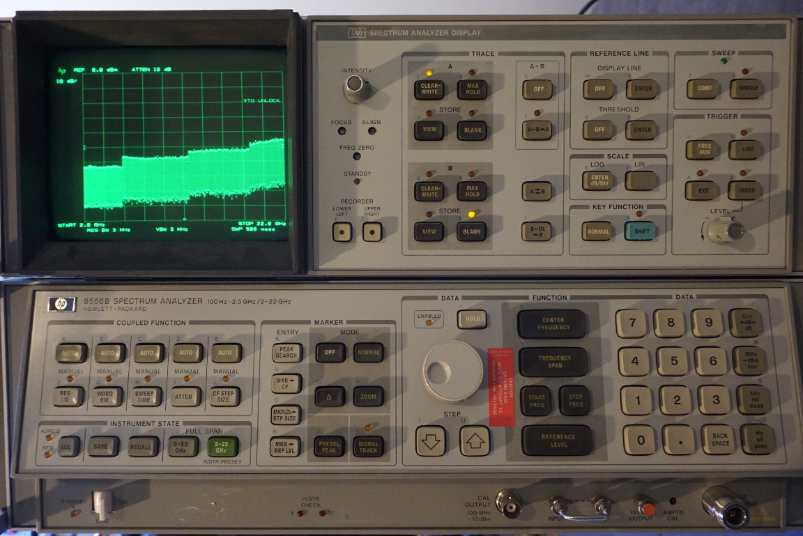
While I was making a video on how to use HP 8671A as the frequency reference for an improved version of my simple DIY tracking generator for my HP 8566B spectrum analyzer, my spectrum analyzer suddenly decided to call it quits and displayed the dreaded “YTO Unlock” message. Although it wasn’t the first time it had done so — other times the “YTO Unlock” message only appeared once in a blue moon and rarely affected any measurements — this time however the problem seemed to be permanent and the error message wouldn’t go away.
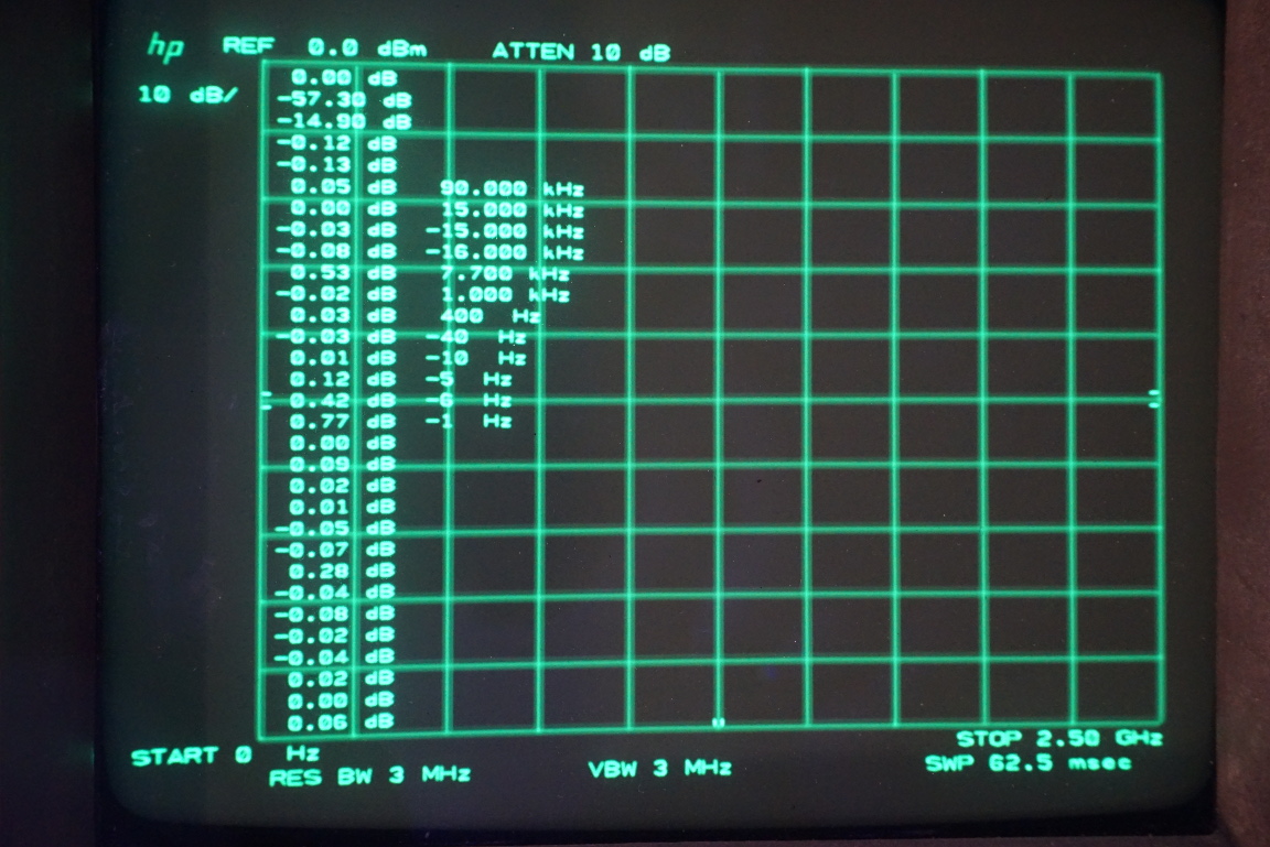
I know that proper repair is long due but because the HP 8566B is so heavy (especially with both the IF/display and RF section linked together), I had hoped I didn’t have to. But with the YTO unlocked, the unit can no longer be self calibrated and the builtin diagnostic routine (see picture below) suggested that something had gone wrong since all the numbers should be close to 0 but the two near the top clearly were not.
I proceeded to opening up the RF section (almost forgot I had done that when I first got it a couple of years ago, you can check out some pictures taken back then):
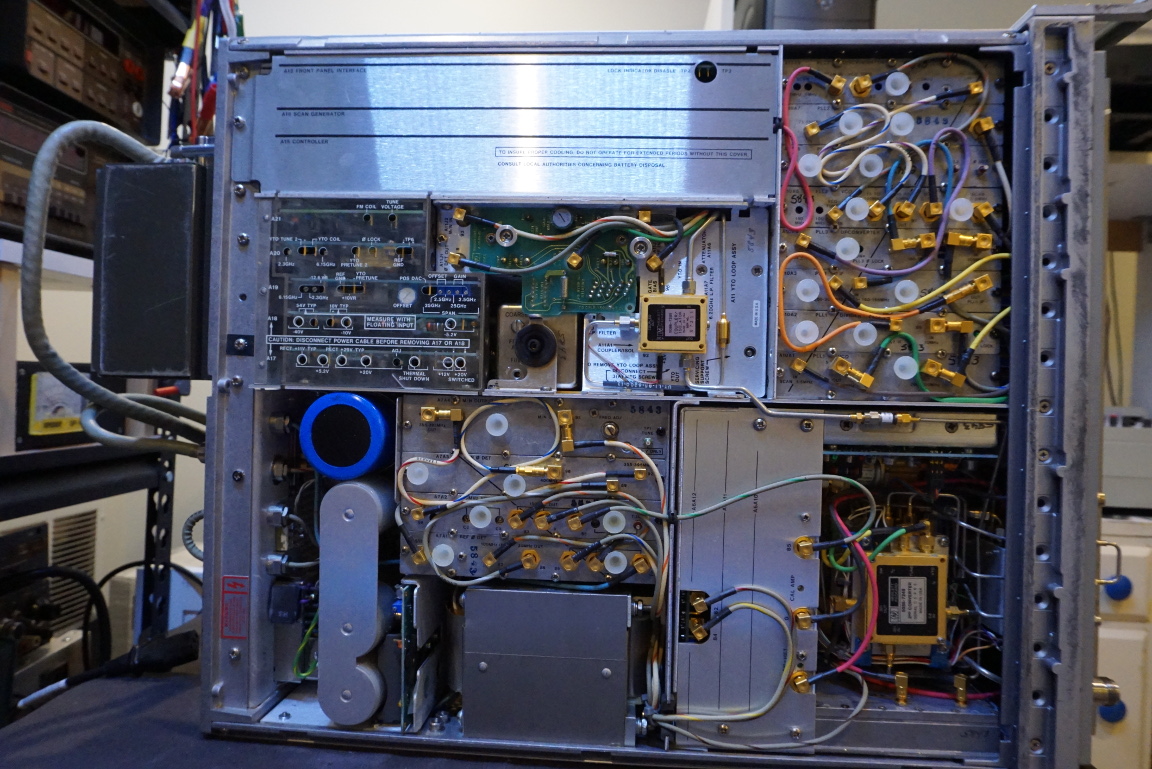
Upon powering up and after the the first glance it appeared that the scope of the problem was quite limited. According to the service manual the possible problem areas for the “YTO Unlock” error include the A19 D/A converter, A20 main coil driver, A21 FM coil driver, A11 YTO loop and the A16 scan generator. While still quite a few subsystems to investigate, it nevertheless limited the areas need to be looked at quite a bit. And most of these boards (except for the YTO loop) can be easily accessed behind the acrylic access door.
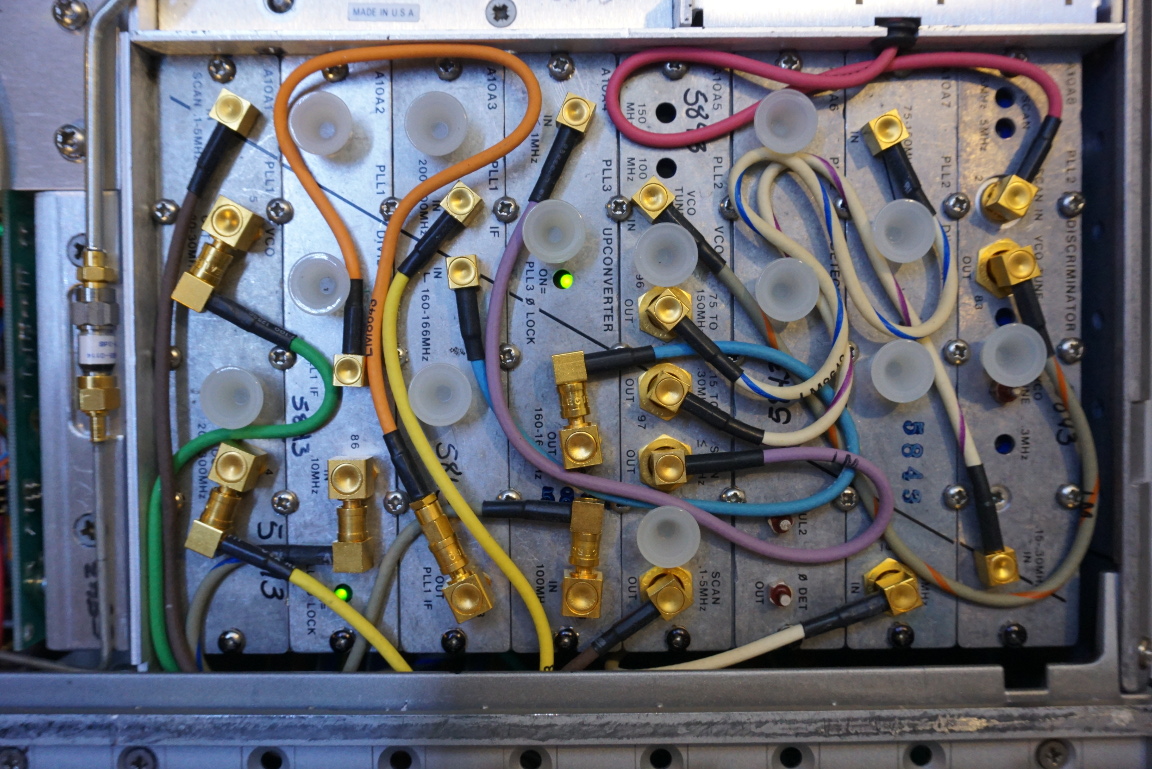
To further confirm that the problem was limited to the YTO subsystem, I confirmed that both phase locked lights on the A6 RF modules and A10 PLL modules are on, meaning that all other loops are in lock.
|
|
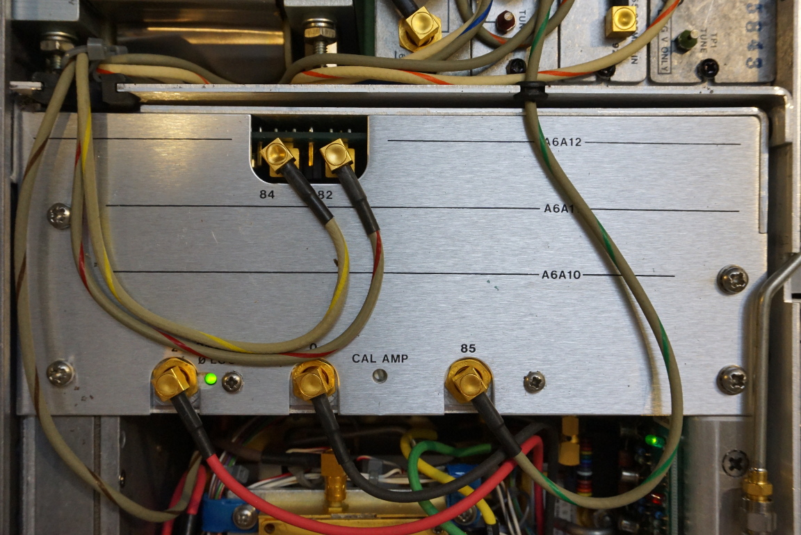
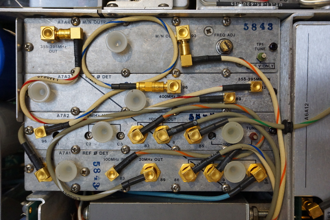
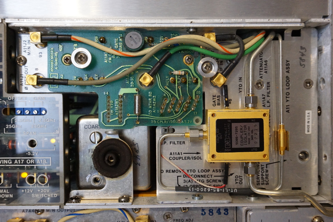
Here are a couple of pictures of the M/N loop reference section and the YTO loop section. One thing interesting you can see from the YTO section is that the ovenized crystal oscillator is sandwiched between two rubber mounts (the other one is at the bottom), this arrangement I believe is to reduce thermal conductivity to the surrounding metal casing and to minimize the impact from environmental temperature changes.
The YTO loop assembly unfortunately is not the easiest to remove and dissemble, so my plan was to eliminate all other possibilities first and look at the YTO loop only as my last resort.
|
|
While I had the RF section panel removed, I decided to take out all of the plugin boards to take a look. As many people have suggested, bad capacitors are the most probable cause.
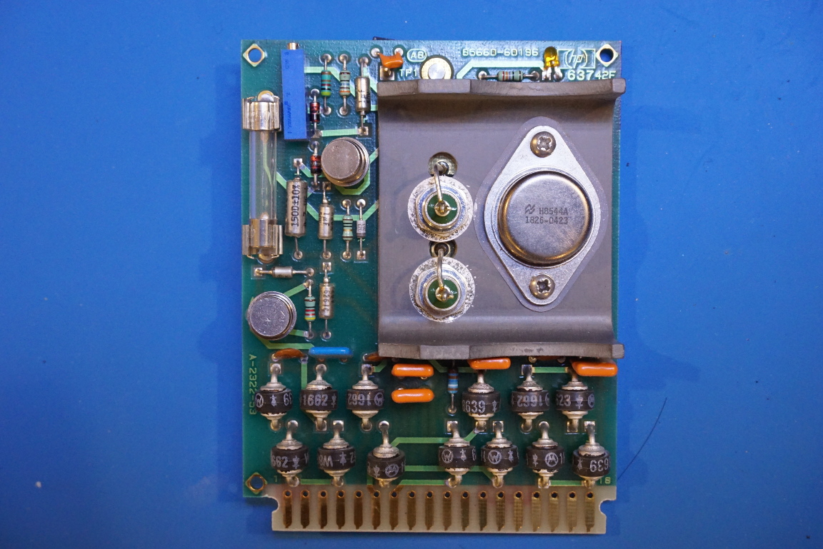
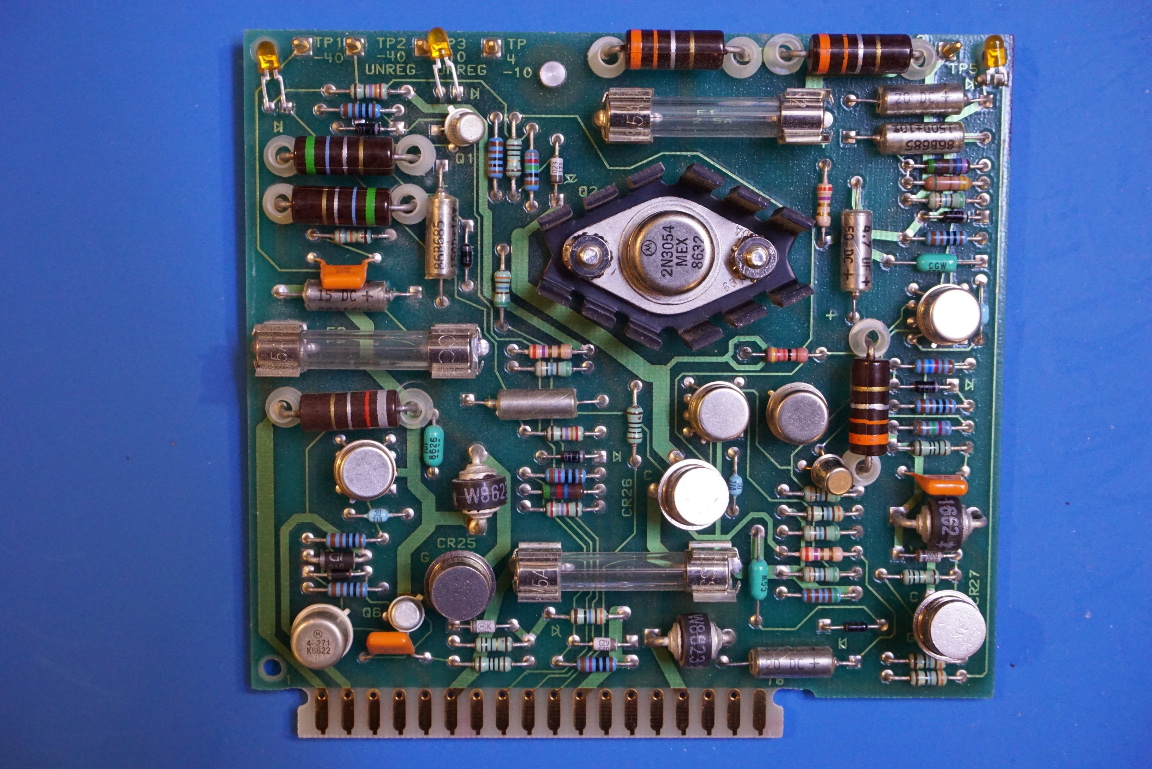
The first board I took out was the main rectifier board. Well most likely everything is fine with this board, I took it out anyway since it was easy to do so plus I already had the panel off. Take a look at those giant rectifier diodes!
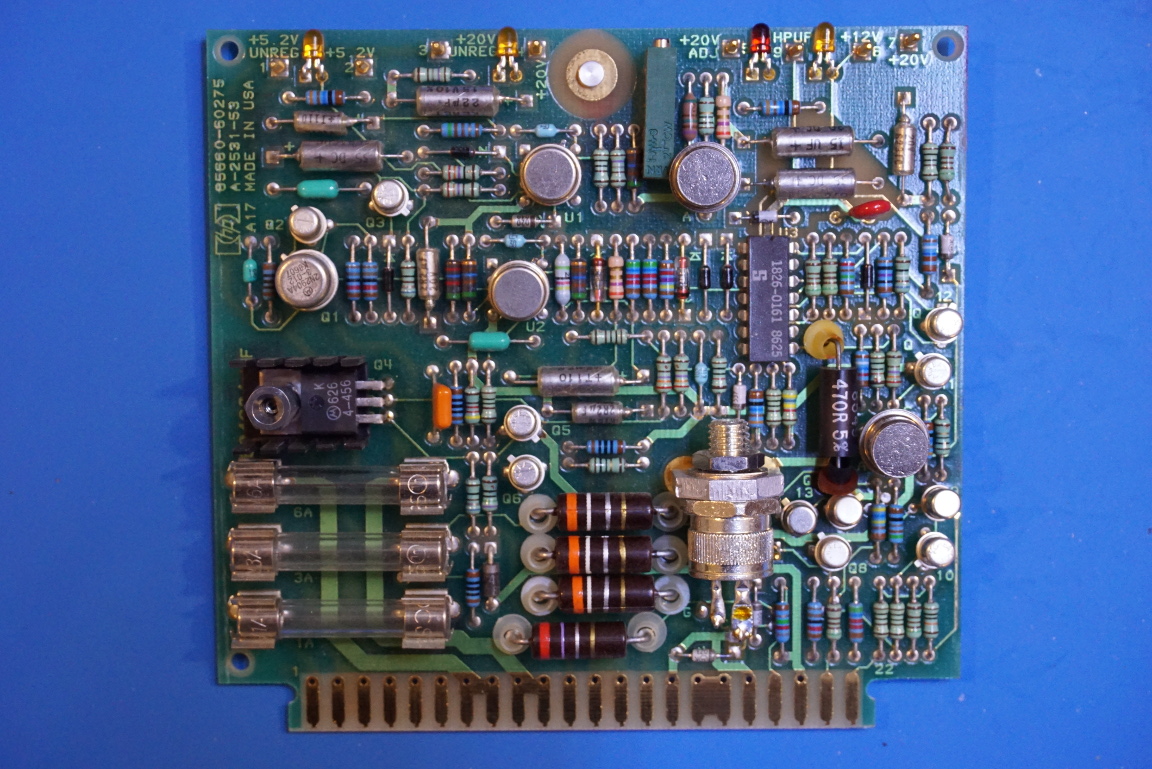
Then I moved onto the boards behind the acrylic service window. Starting from the bottom the first board is the positive power supply board (on the left) and the next one is the negative supply board (to the right):
|
|
While stilled powered on, I measured the various test points voltages on the supply boards and the voltages are mostly fine. Two values are a little bit off. One is the 11V test point on the positive supply board, which measured at around 10.5V and the other is the 18V test point (referenced to the -10V) on the negative supply board, which only measured at around 15.6 V. But the -10V was pretty much bang on. All components on these boards passed the visual inspection so I decided to leave them alone for the time being.
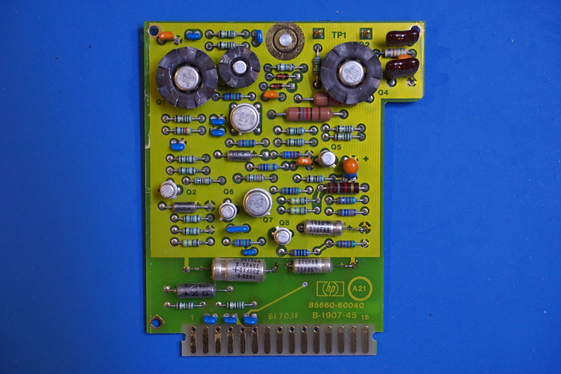
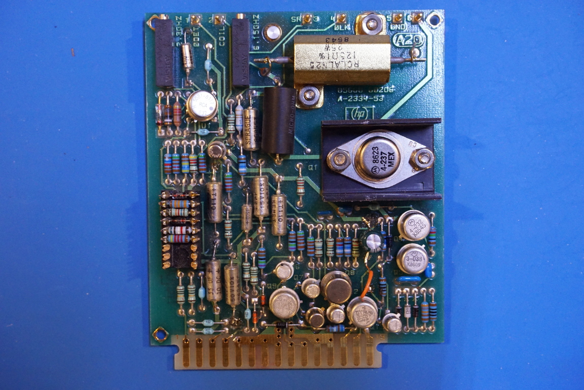
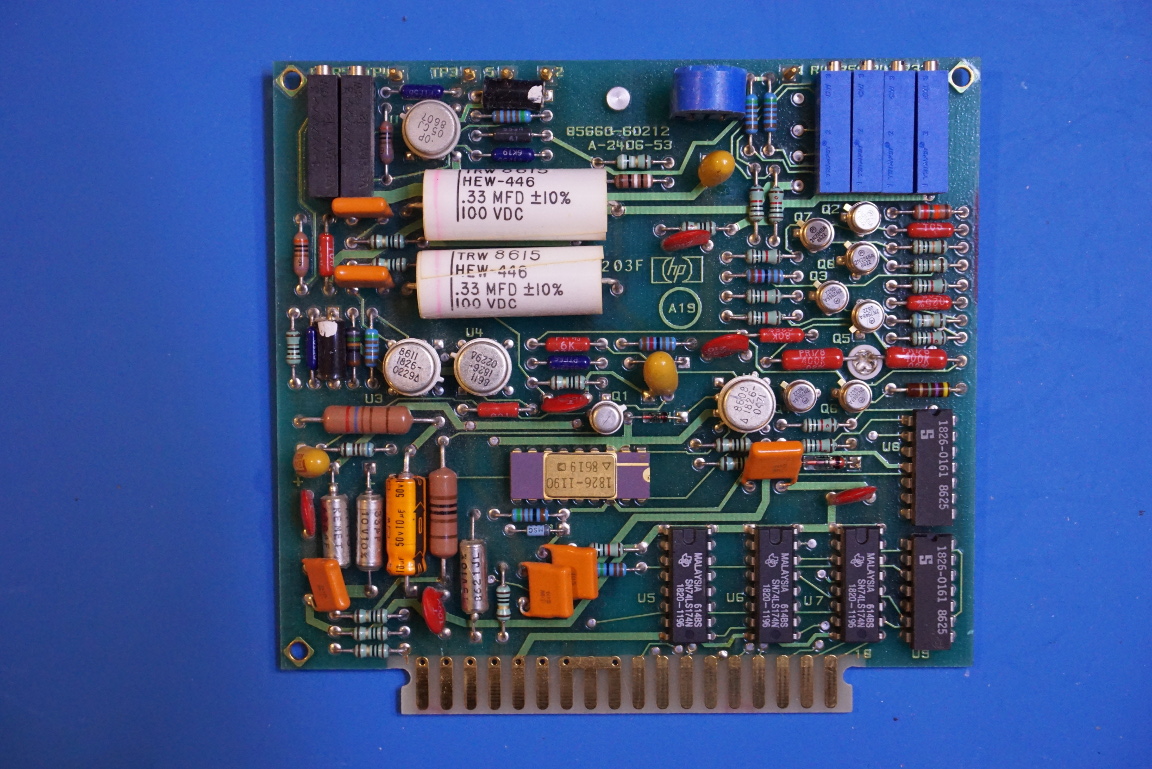
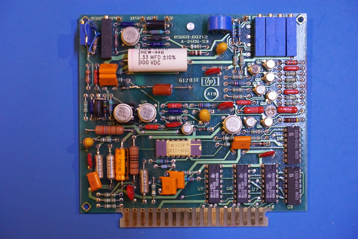
The remaining three plugin boards are the A21 FM coil driver, A20 YTO driver and A19 the digital to analog converter. The picture below shows the FM coil driver board. All the capacitors on this board looked fine and upon further testing all values and ESRs turned out to be within tolerance.
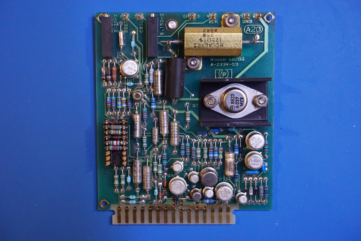
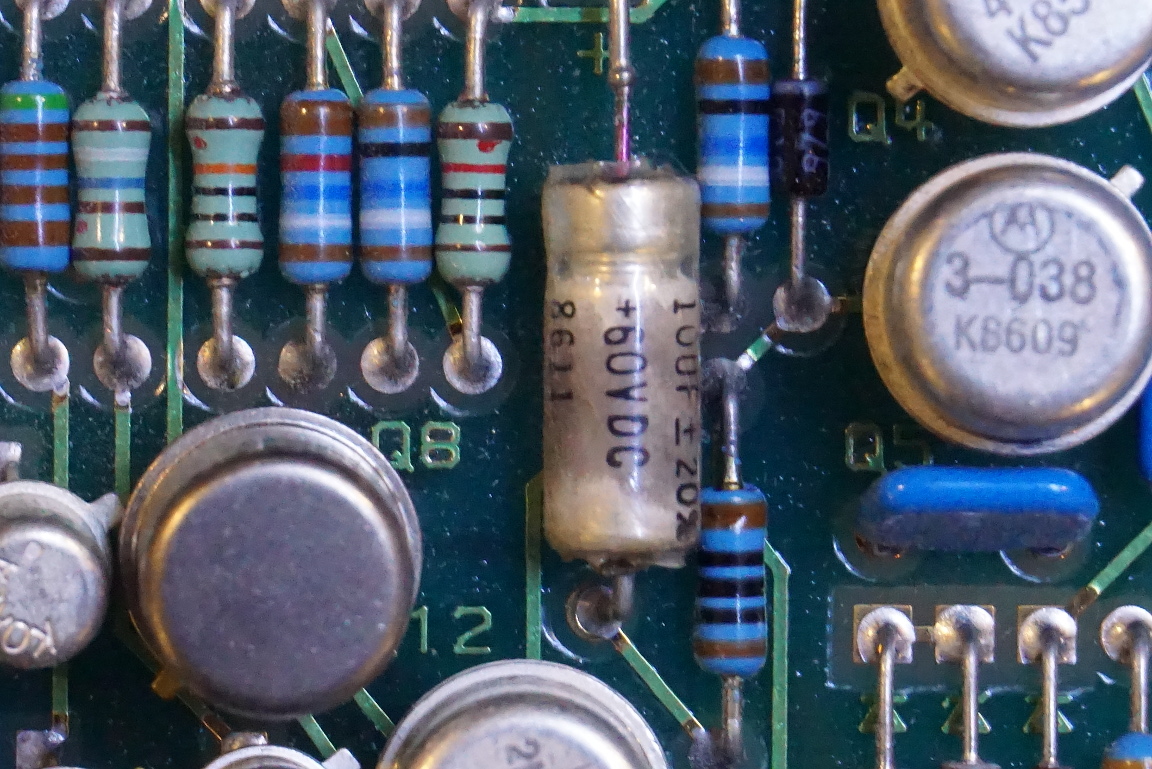
The board under the A21 FM coil driver is the A20 YTO driver board. Upon close inspection, one capacitor looked quite suspicious. I was very happy to see this as it further reinforced the theory that the YTO unlock issue was caused by some bad capacitors.
|
|
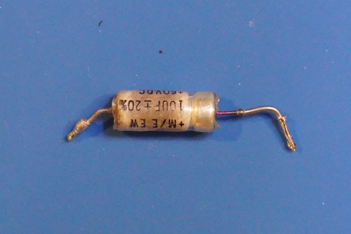
I desoldered this leaked capacitor and while its capacitance still measured at around 10µF, its ESR was more than 50Ω. So I replaced it with a 10µF 100V capacitor (the original one is rated for 60V) and hoping this would solve the YTO Unlock problem.
|
|
But it did not. The “YTO Unlock” message was still there when I powered up the spectrum analyzer with the cap-replaced A20 YTO driver board reinstalled.
Then I remembered that while measuring various test points voltages, I came across the -12.6V on the A19 DAC board and it was only reading -12.4V. After reviewing the service manual, I realized that this value must be precisely -12.6V as this is the voltage used for YTO pretuning. So the 200 mV variation was simply too large for the tuning circuitry to compensate and thus causing the YTO to become unlocked.
So why the voltage was off from the -12.6 nominal value? As it turned out, when measured at the test point (TP4), the voltage reading seemed to drift a little bit. And while I was attempting to adjust the potentiometer, I noticed that the measured voltage jumped quite a bit. Sometimes by just applying slight pressure on the adjustment screw without turning it caused the measured voltage readings to jump wildly. So it became clear that the potentiometer must have failed due to its old age.
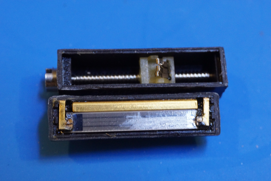
The potentiometer used here is a Bourns 2K low tempco (15ppm) one. And after I removed it from the board I confirmed that the wiper indeed was not making good contact. So I opened it up and was hoping I could clean it and repair it. From the picture below you can see that the surface of the potentiometer was badly scratched up. Unfortunately, the resistive film on the substrate is very thin, even gentle cleaning caused the resistive material to flake off.
Since I didn’t have any precision potentiometers of the same kind lying around I had to substitute with the components I have. Looking at the circuit diagram though, it seemed that the actual value of the potentiometer is not super critical, as it was simply used in the feedback loop of the non-inverting amplifier to obtain the -12.6V from a 6.2V Zener diode. So I ended up using a cheap 5K 10-turn trim-pot paralleled with a 3.3K resistor as the replacement. This way although there is a bit more non-linearity introduced the overall resistance stays at roughly 2K. Even without the paralleled 3.3K resistor the replacement probably would’ve been just fine.
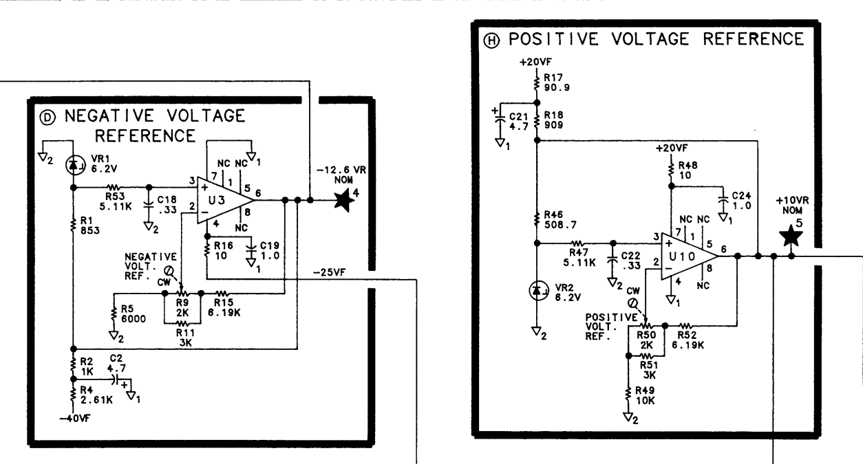
I also painstakingly measured every single capacitor’s ESR on the DAC board. And while the ESRs all measured good, the capacitor connected to the positive input of the negative voltage reference OpAmp (C18) seemed to be a bit low. I am sure I could have just left it as is since its value has little impact on the performance of the OpAmp. But I replaced it with another one just in case problem develops down the road.
Here is a picture of the board after the potentiometer and the input capacitor had been replaced.
After replacing these components, the YTO unlock error was gone and my HP 8566B was back in working order again. I left the unit on overnight to see how stable the -12.6 V was and even without the low tempco potentiometer the voltage variation stayed well within a few mV. Although I might change the potentiometer to a proper low tempco one like the original one sometime later, the spectrum analyzer is fixed for now.
In the video below, I documented the repair process along with my reasoning at each step of the way.

