In my previous blog posting, I did a teardown of a LogiMetrics A300/S 2 to 4 GHz Traveling Wave Tube Amplifier (TWTA). After doing the teardown, my focus immediately turned to troubleshooting the unit and hopefully restoring the unit back into working order again.
The first thing I was able to fix was the stuck relay. After some researching, it turned out that this relay is a latching relay. During normal operation, the relay coil is not energized. In a fault condition (e.g. over-voltage or over-current), the control circuitry output triggers the relay coil and this pulse signal causes the relay to trip and disconnect the high voltage supply to the TWT. Once tripped, the HV circuitry would remain be disconnected until the popped-up button is pushed back in again and thus causing the the relay to reset.
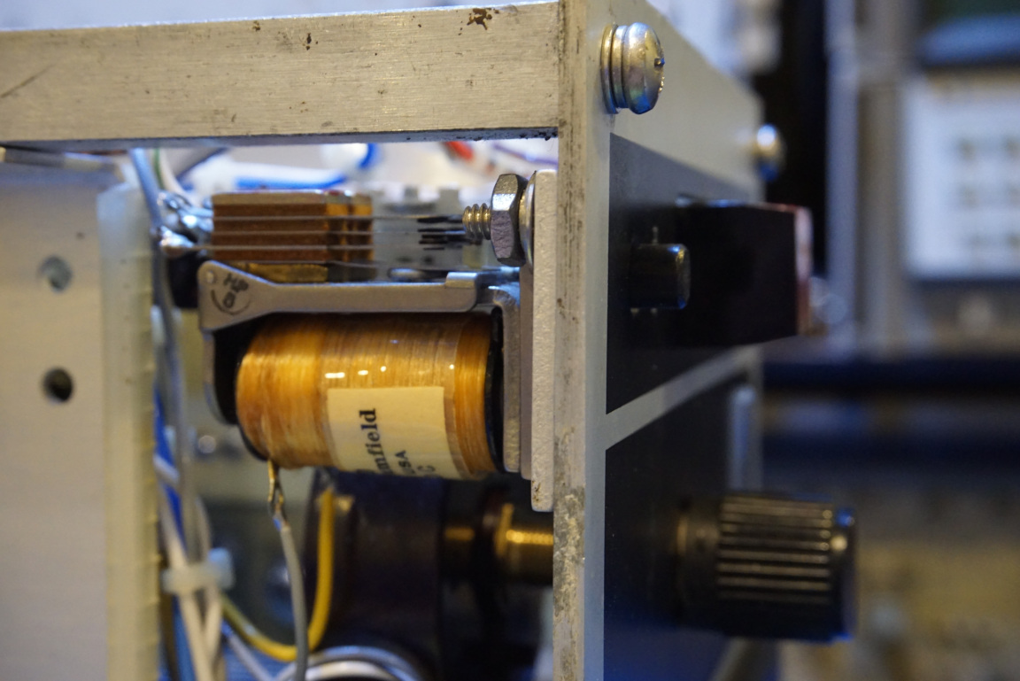
As it turned out, the relay is stuck in place since it hadn’t been actuated for years. After repetitively spraying with some electric cleaner, the relay was finally unstuck.
Also as I mentioned previously, some of the capacitors also appeared to be in questionable state. Since I do not have any schematics for this TWTA, the best I could do is to measure each component I could test with a multimeter or LCR meter and verify that at least everything is working at the component level.
Originally, as some of my readers suggested, the high voltage capacitors seemed have gone bad as the heatshrink tubing around some of these capacitors seemed to be soaked in some kind of oily substance.
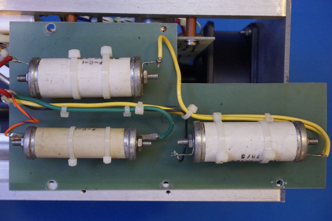
But after removing these capacitors from the circuit, they measured to be very close to the nominal value and also had reasonable ESRs. So I decided to leave them along.
Some electrolytic capacitors on the main circuit board however are definitely faulty. A few of the original capacitors had ESR way over 1 kΩ.
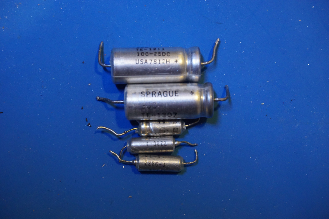
Not all original capacitors were faulty however. In fact, some are even better than the capacitors I have in my component bin. So I left those capacitors alone. It is quite amazing knowing that some of these capacitors have been there for more than half a century and are still working!
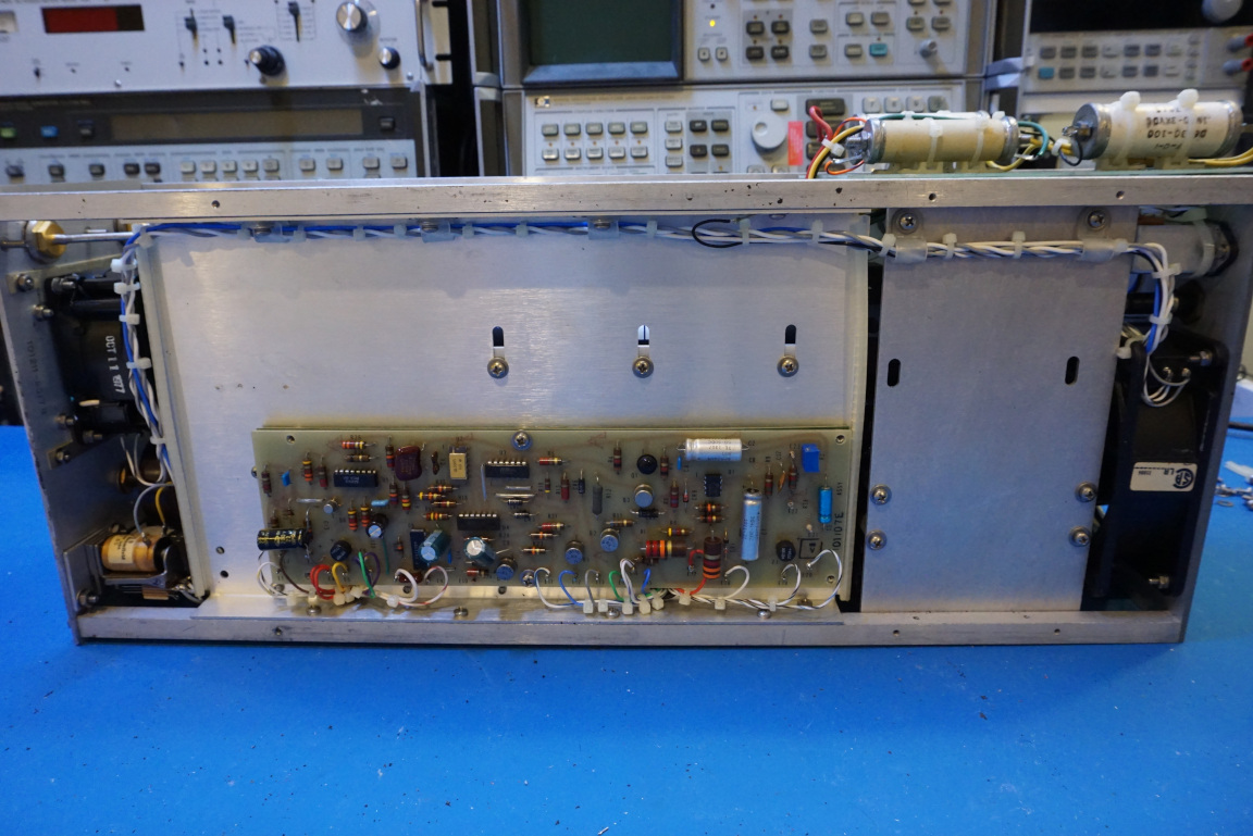
Here is a picture of my temporary repair. I say temporary because I did not have any properly sized capacitors. The ones I happen to have are higher in voltage ratings. While they should be fine, their physical sizes turned out to be too large for the case to close properly. I will need to swap them out once the proper sized ones come.
Of course, the remaining wildcard is the traveling wave tube. After all, it is the key component inside this TWTA. If the tube had failed then all my previous repairs would not have mattered.
Luckily, the TWT itself seemed to be nice and strong and after I verified all the components I could get my hands on, I replaced the fuse and powered up the TWT for the first time.
In the picture below, you can see that the TWT has a gain of roughly 30 dB. And by further increasing the helix current, the gain started to level off and eventually dropped quite a bit.
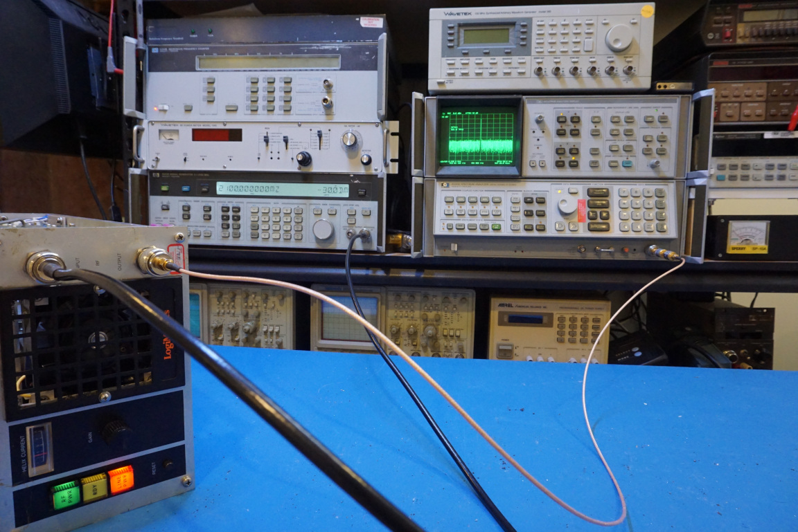
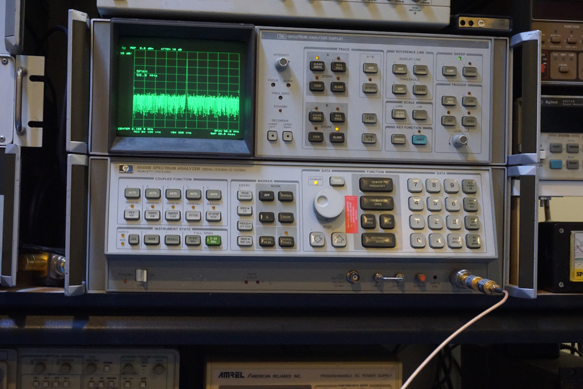
Here is a picture showing the amplified -30 dBm 2.1 GHz signal. I did not have an attenuator that could dissipate 20+ watts so I did not test the TWT for its maximum output power.
Finally, here is a video showing the testing of this repaired TWT.

