A fuse is a sacrificial device for the protection the rest of the circuit in an over-current situation. There are situations we need to know with some reasonable confidence what the actual maximum current is for a given fuse without destroying it. This is beneficial when the specifications for the fuse at hand is unknown (e.g. with cheap no-name brand fuse), or the circuitry to be protected is so critical that the interrupt current level must be specified precisely.
Obviously for resettable fuses (such as PPTC fuse or polymetric PTC fuse), the rated current can be easily tested repetitively. Thus the focus here is for glass fuses and HRC fuses.
This non-destructive testing of fuses can be accomplished by analyzing the properties of the fuse material. In practice, all fuses are made of metal alloys with positive temperature coefficients, the resistance of which is governed by the following equation:
\[R_t = R_{t_0}(1+\alpha\Delta T)\quad\quad where \quad\Delta T=T-T_0\]For the majority of the fuse materials, the temperature coefficient is roughly in the range between 0.003 to 0.004 per Kelvin. Assuming the temperature coefficient is 0.004 per Kelvin and we can get the following equation by re-arranging the terms:
\[\frac{R_t}{R_{t_0}} = 1 + \frac{\Delta T}{250}\]Since ΔT is the temperature difference between the operating temperature and the room temperature (T0 = 20°C), and for T >> T0:
\[\frac{R_t}{R_{t_0}} \approx 1 + \frac{T}{250}\]The above equation suggests that if the fuse temperature is at 250 degrees, the measured resistance would double that at the room temperature and if the fuse temperature is at 500 degrees the measured resistance would tipple. When using a constant current source, the voltage measured at the terminals of the fuse is proportional to the fuse resistance.
Although we do not know the actual composition of a given fuse material and thus do not know the exact temperature coefficient or the melting point precisely, we can use the above equation to calculate the maximum current rating of a fuse with reasonable accuracy as when the current approaches the maximum, the thermal run-away causes the fuse resistance to rise exponentially and thus once the resistance doubles, it only takes very little current increment for the fuse resistance triple and eventually causes the fuse to fail.
For most of the fuse material, the melting point is relatively low, so it is reasonable to assume that the melting temperature is at between 250 and 750 degrees. And once the fuse resistance has doubled, the additional current increment needed for it to fail is usually less than 10% to 20%.
For the experiment setup, I used a high current power supply in conjunction with an electronic load to provide the constant current. And a multimeter is used to monitor the voltage drop across the fuse:
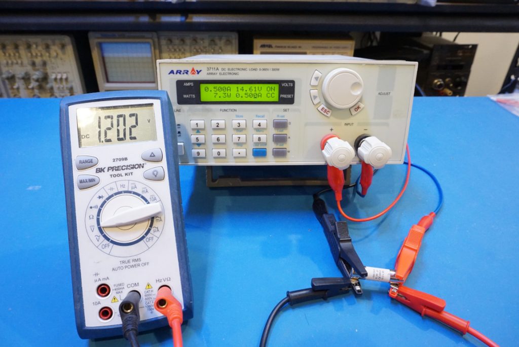
Here’s the data captured using a generic 1A glass fuse:
| Current (A) | Voltage (V) | Rt | Rt/Rt0 |
| 0.10 | 0.02 | 0.15 | 1.00 |
| 0.20 | 0.03 | 0.15 | 1.00 |
| 0.30 | 0.05 | 0.15 | 1.00 |
| 0.40 | 0.06 | 0.16 | 1.03 |
| 0.50 | 0.08 | 0.16 | 1.07 |
| 0.60 | 0.10 | 0.17 | 1.13 |
| 0.70 | 0.13 | 0.18 | 1.21 |
| 0.80 | 0.16 | 0.20 | 1.32 |
| 0.90 | 0.20 | 0.22 | 1.48 |
| 1.00 | 0.26 | 0.26 | 1.75 |
| 1.10 | 0.37 | 0.34 | 2.24 |
| 1.20 | 0.61 | 0.51 | 3.37 |
| 1.30 | 1.29 | 0.99 | 6.62 |
In the video included towards the end of this post you can see that at 1.3 A the fuse was glowing red hot and would mostly like to fail at that current level for prolonged period of time.
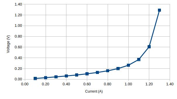
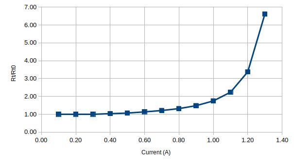
Below are two plots of the current versus voltage and current versus resistance ratio respectively for the 1A fuse:
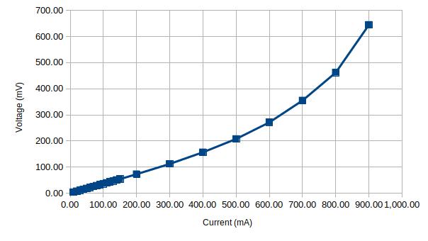
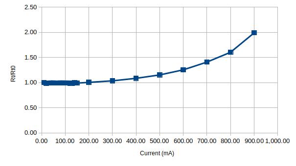
When testing another glass fuse (rated for 0.1A) that I bought from the same vendor, the result was somewhat shocking. As you can see in the figures below, the fuse’s maximum current limit is almost ten times that of the rated current. This is another reason why this kind of non-destructive testing is useful as this fuse would not be useful at all for a circuit that requires a 0.1A fuse.
Finally, I tested an HRC fuse that is rated for 630mA. Since HRC fuses are sand-filled, they have a rather large thermal capacity and it takes several minutes for the fuse temperature to stabilize at each current point:
| Current (A) | Voltage (V) | Rt | Rt/Rt0 |
| 0.10 | 0.18 | 1.79 | 1.00 |
| 0.20 | 0.36 | 1.80 | 1.01 |
| 0.30 | 0.55 | 1.84 | 1.03 |
| 0.40 | 0.77 | 1.93 | 1.08 |
| 0.50 | 1.02 | 2.04 | 1.14 |
| 0.60 | 1.31 | 2.18 | 1.22 |
| 0.65 | 1.48 | 2.28 | 1.27 |
| 0.70 | 1.71 | 2.44 | 1.36 |
| 0.75 | 2.02 | 2.69 | 1.50 |
| 0.80 | 2.39 | 2.99 | 1.67 |
| 0.85 | 3.00 | 3.53 | 1.97 |
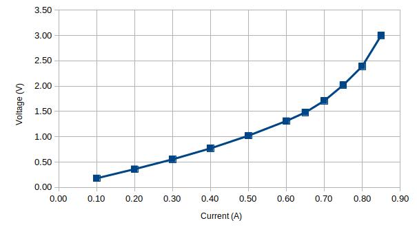
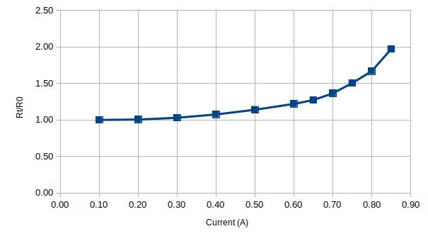
According to the graphs above, this particular fuse will most certainly blow at around 900 mA.
The following is a video of this experiment:

