In the area where I live, the cell phone reception is spotty at the best. Even though I am only a couple of miles from a nearest tower, I barely get any cell signal at all let along usable 4G coverage. Since nowadays everyone is working from home, I thought it would be a good investment for a cell signal booster so that in the event I loose my network connection I can continue working tethered to my phone.
After some extensive research, I settled on Nextivity’s Cel-Fi Go X signal booster. What attracts me the most is its ability to amplify a single carrier’s signal up to 100 dB. This is important given how weak the signal is around here. Although Cel-Fi Go X claims to be able to cover an area up to 15,000 ft², I suspect the actual coverage area would be significantly less given the signal reception.
Under FCC regulation (Part 20.21), a signal booster’s maximum gain is capped at 80 dB for the cell phone signal bands. The Cel-Fi Go X gets around this by only amplifying a single carrier’s signal at any given time.
Commercial cell phone signal boosters like this one are not just simply broadband signal amplifiers. For the Cel-Fi Go X, it is designed to specifically amplify 4G cell phone signals only when reference signals within the frequency bands are detected. All commercial boosters also have to go through extensive conformance testing before they can be certified on carriers’ networks. If you are interested in these testing procedures, you can check out ETSI‘s conformance testing documents like 3GPP TS 36.143 Rel.10.
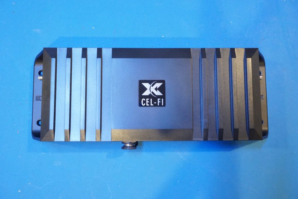
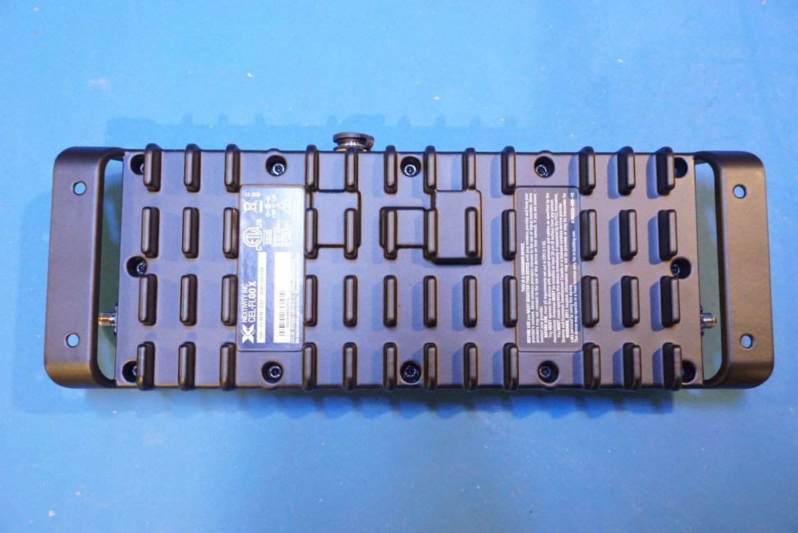
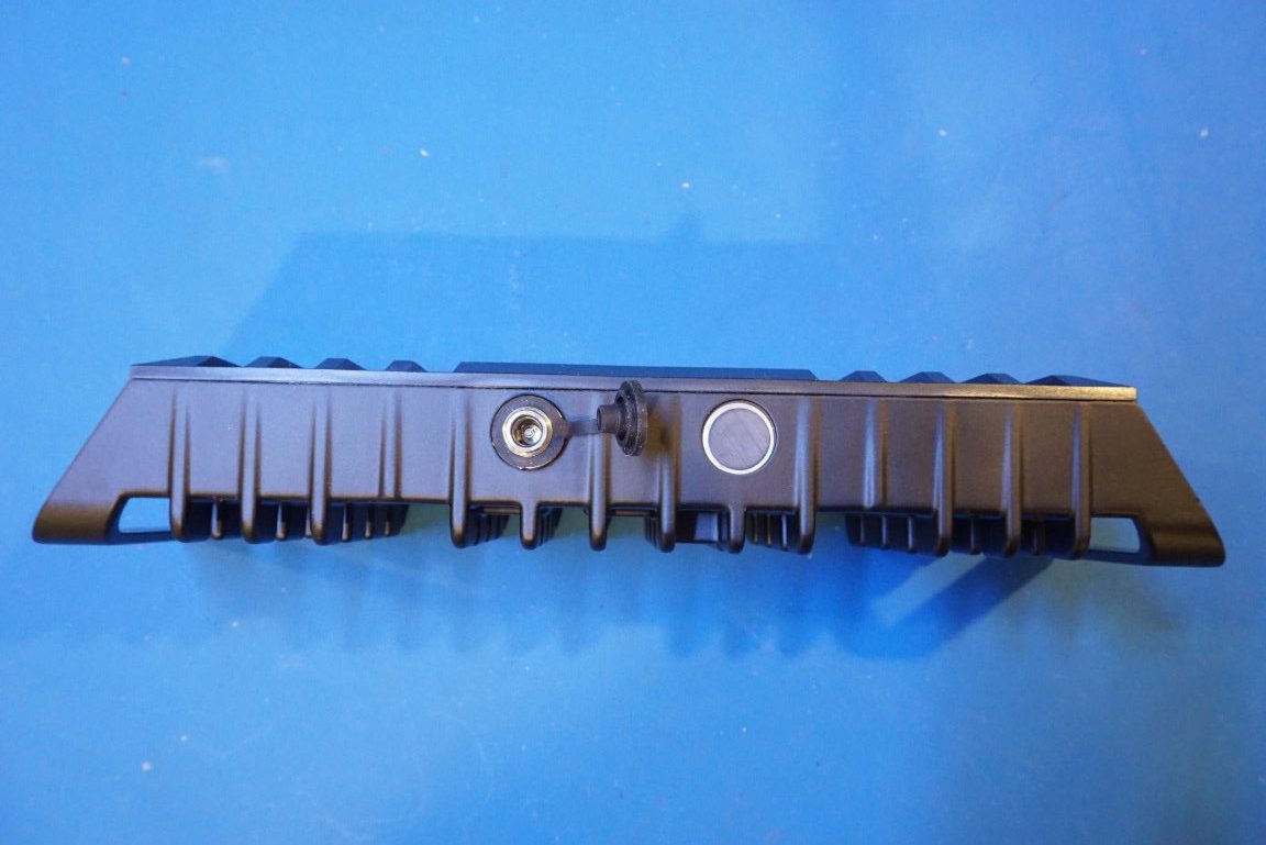
The unit is passively cooled and enclosed in a beautiful extruded aluminum case. It is NEMA 4 rated and thus is suitable for outdoor use. It is powered by an external 15V 1.6A power adapter with a sealed twist-on type connector.
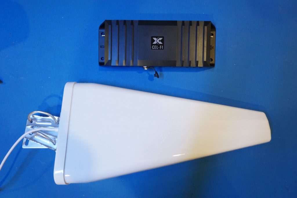
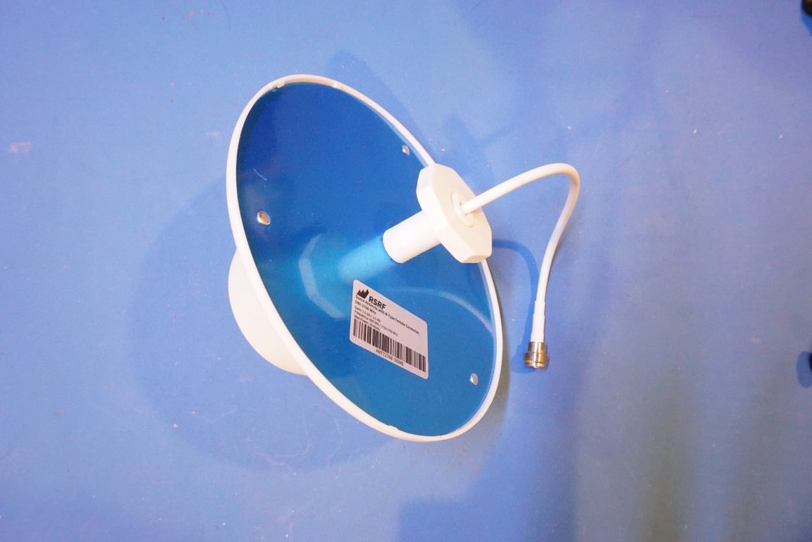
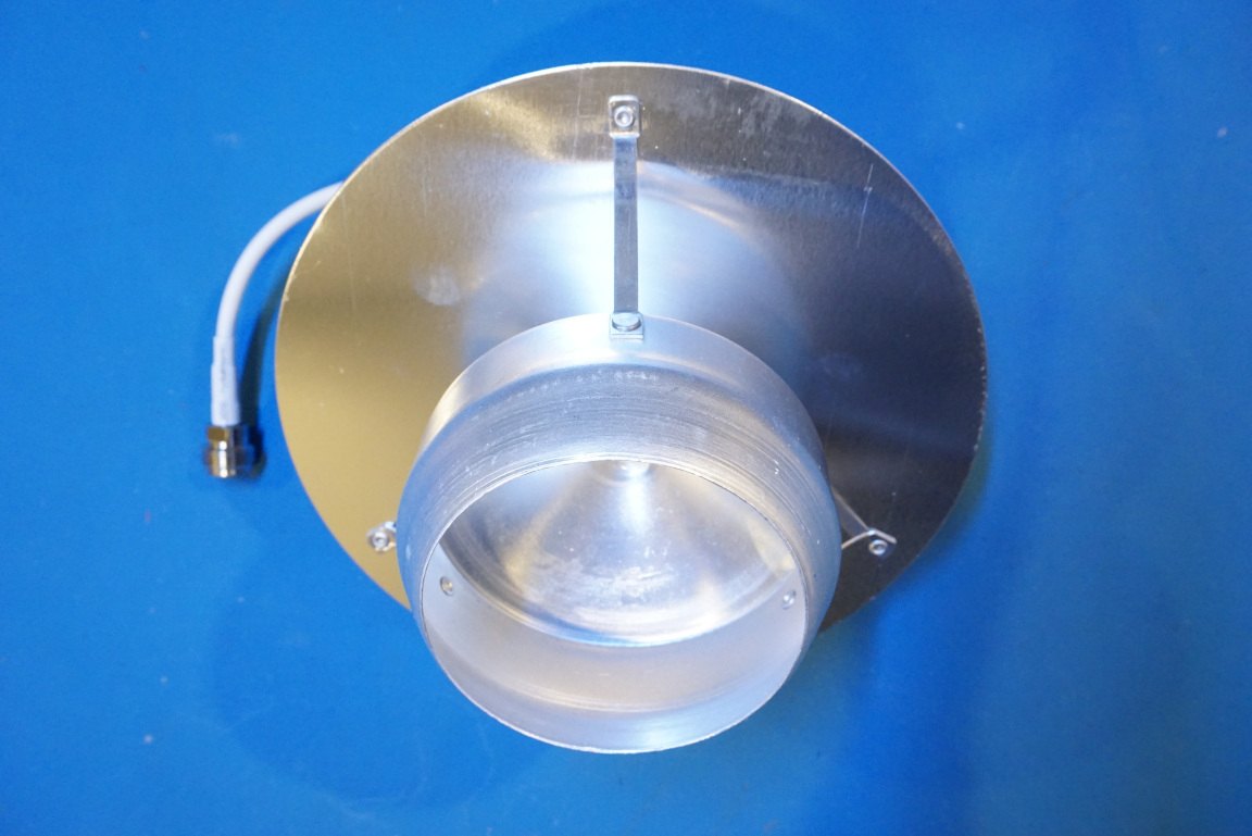
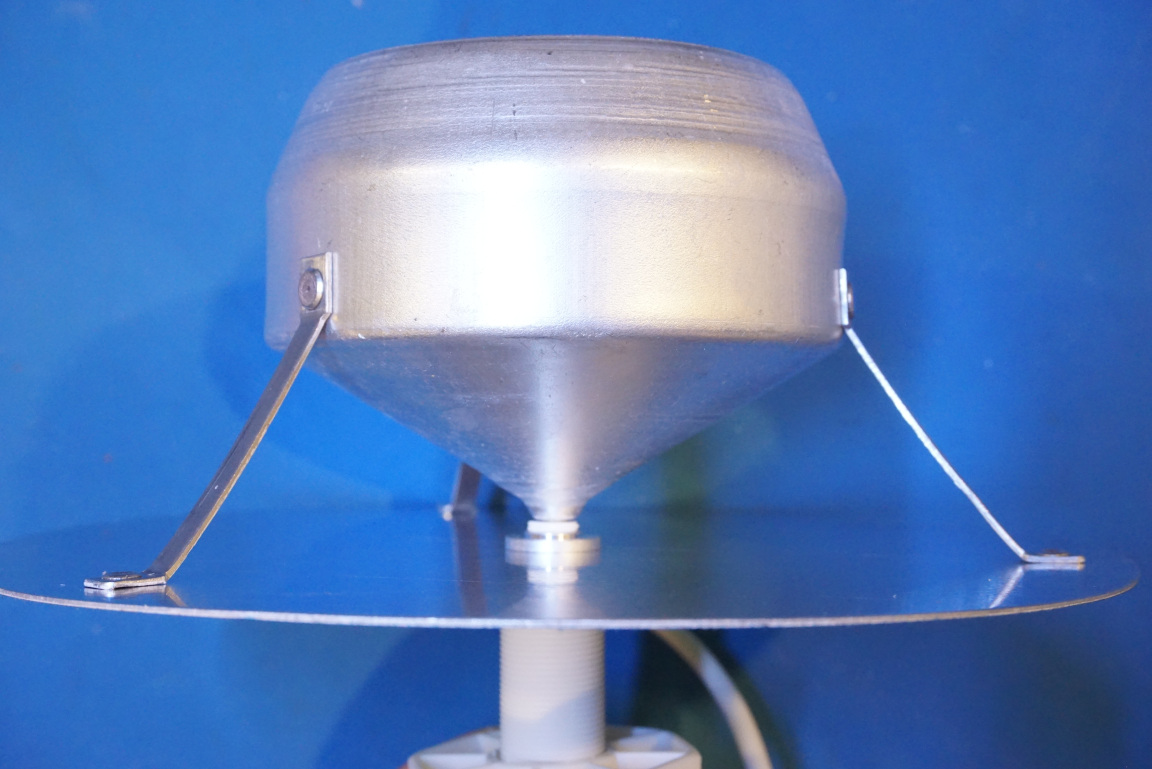
The kit comes with an outdoor LPDA (Log Periodic Dipole Array) wide-band high gain directional antenna. Don’t confuse this with an Yagi antenna, which has a relatively a narrow bandwidth. The main difference betwen these two types of antenna is that in an LPDA all elements are actively driven and its wide bandwidth is attributed to the different lengths and spacing of the dipole arrays. Whereas for a typical Yaggi, there is only a single driven element and all the directors and reflectors are passive elements.
The picture below gives you an idea of the size of the antenna in relation to the amplifier unit.
There are a few different options for the indoor antenna. I chose the standard omnidirectional dome antenna given that I have a relatively small house and a single antenna should be able to cover the entire space.
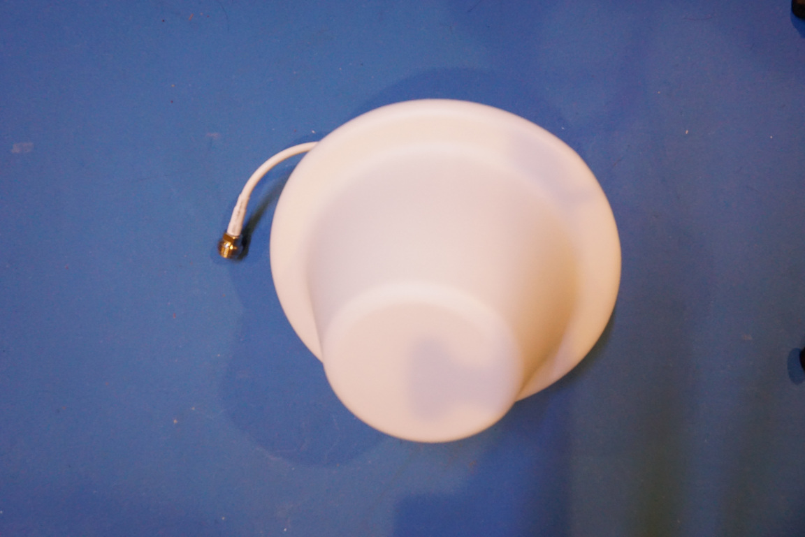
The dome antenna is a broad band antenna. It has a frequency range between 698 MHz and 2.7 GHz. After removing the enclosure, you can see that this is essentially a vertically polarized, modified monocone antenna. The high bandwidth is achieved via the graduated cylindrical cross section.
Now moving to the main unit. The top cover is made of plastic. It cannot be fully shielded since the Cel-Fi Go X uses bluetooth to communicate with an cell phone application for controlling and monitoring the device.
Both the uplink and downlink side of the circuitry are shielded.
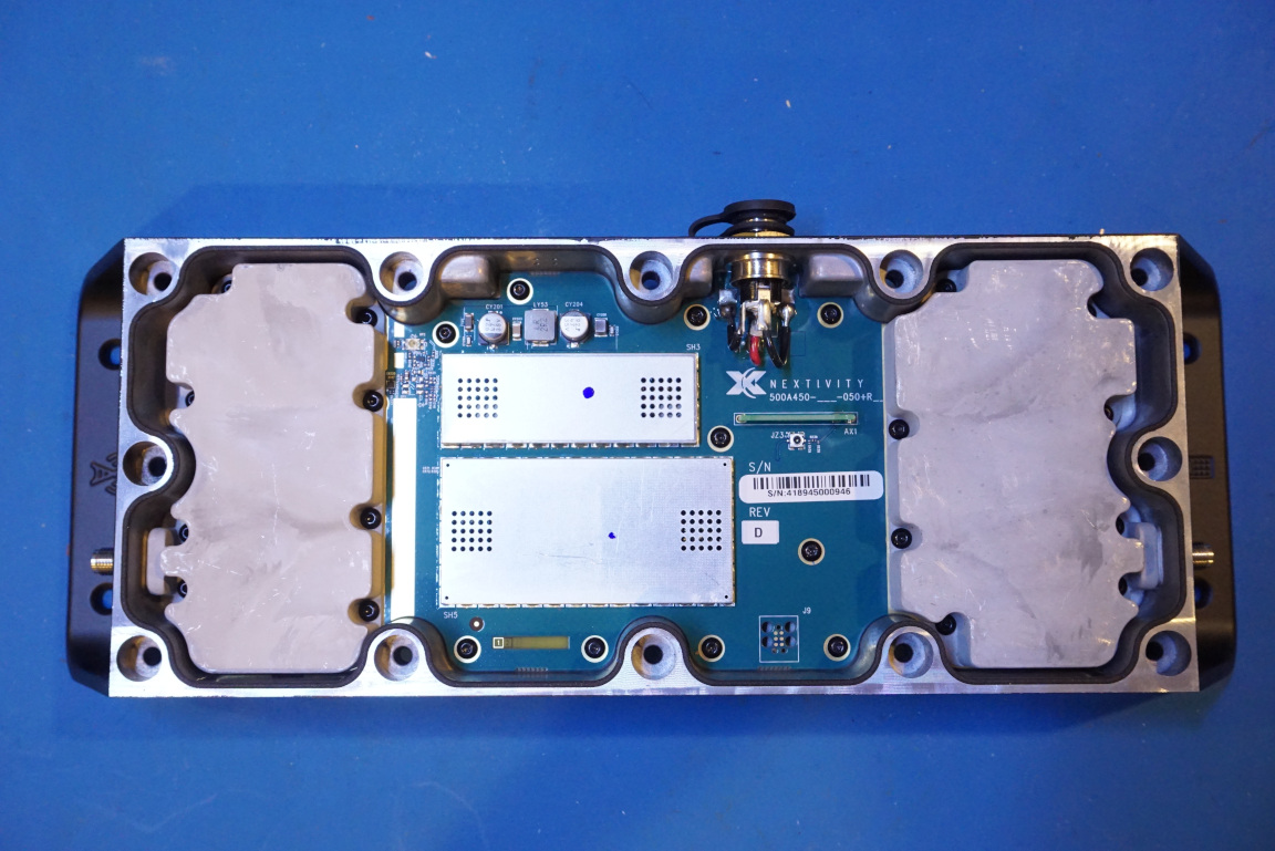
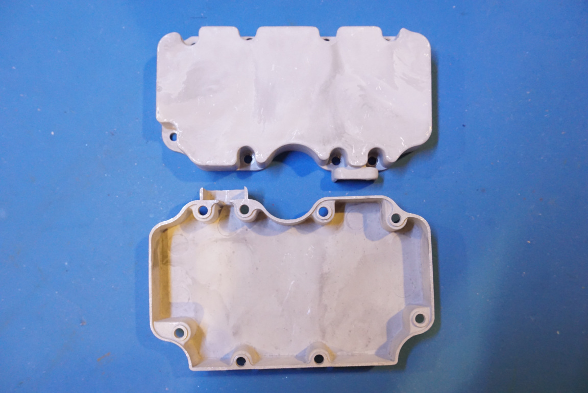
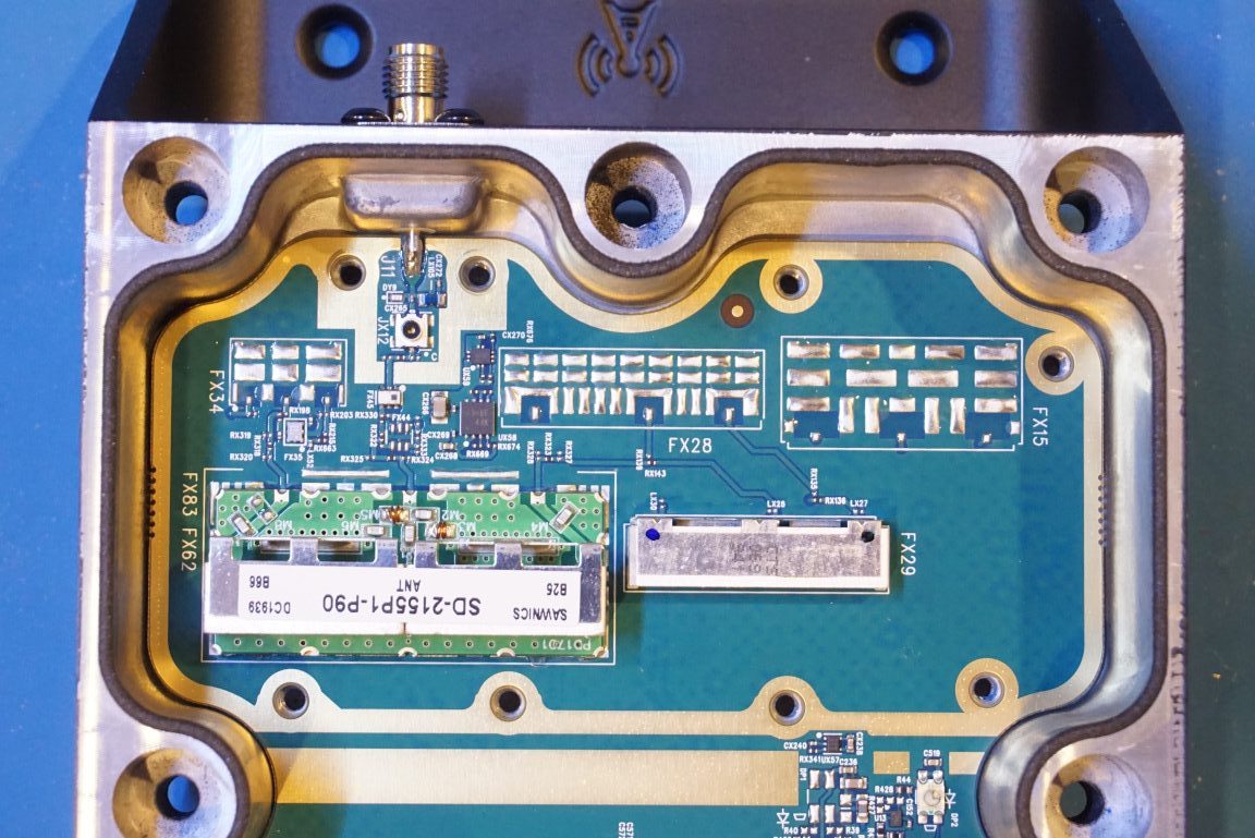
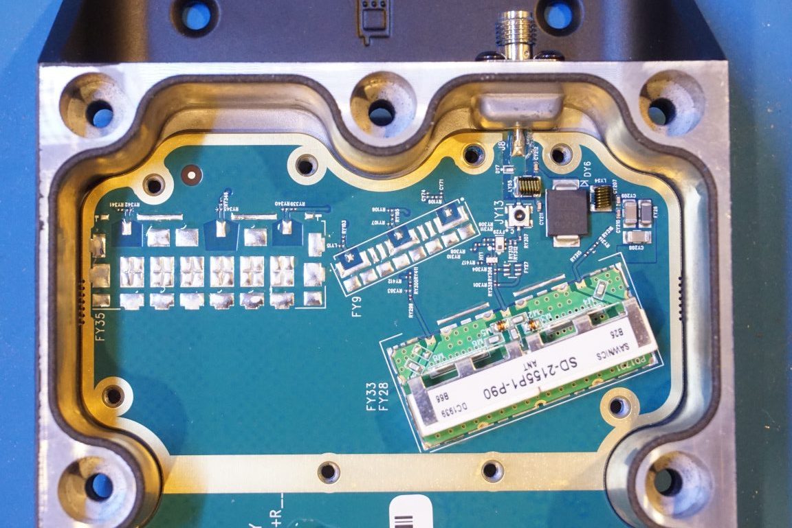
Here are a couple of pictures showing the interior of the unit with the shielding cans removed. The left side is the RF section for the uplink (donor antenna), the right side is the RF section for the downlink (broadcast antenna).
Judging by the marking on the PCB, it looks like that the PCB used here is at least a six layer board.
According to the datasheet, Cel-Fi Go X supports two sets of radios which are capable of covering both lower band (sub 1 GHz) and higher band (2 GHz) simultaneously.
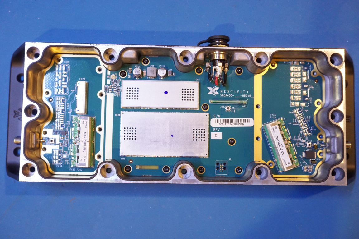
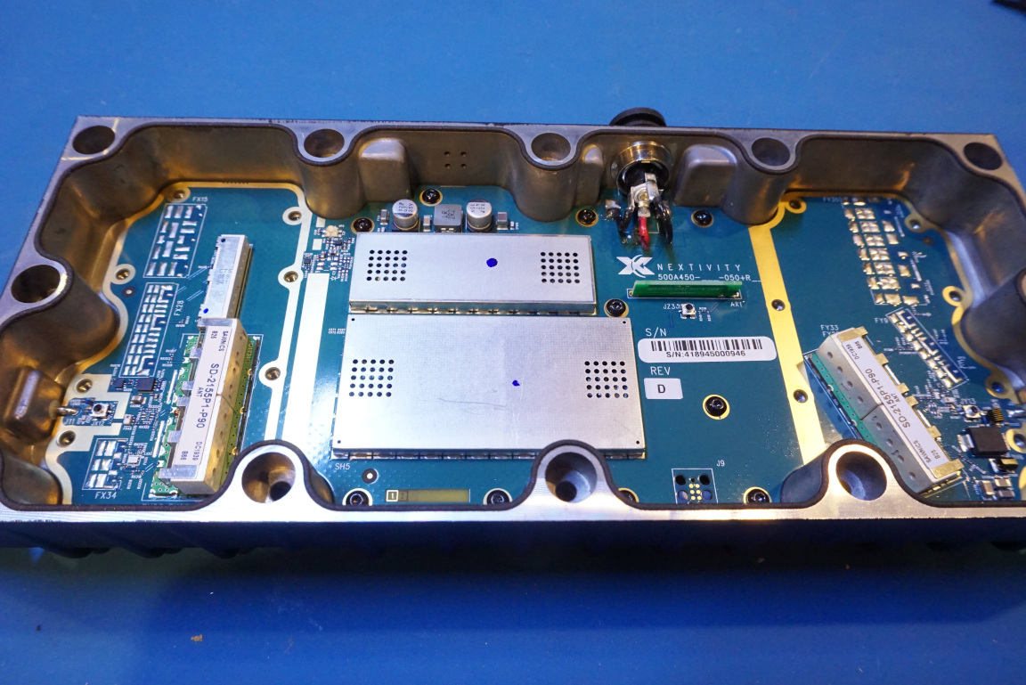
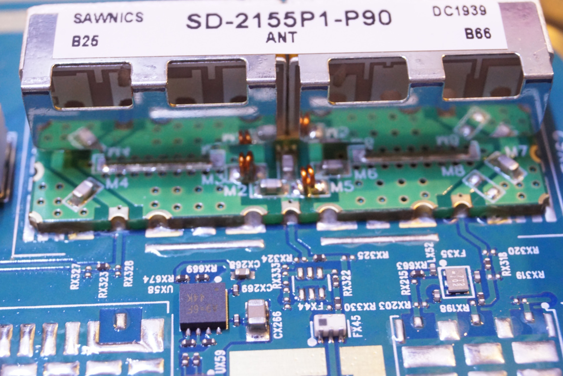
Here are two closeup pictures for the donor antenna side (external antenna) of the RF circuitry.
I could find very little information on the components used here. The SAWNICS module looks like a duplexer as cell phone boosters operate in duplex mode. The smaller module to the right marked with “CTS” could be a RF filter. And the smaller 6-pined SMD chip might be a SAW filter perhaps? The black SMD could be a variable gain low noise amplifier given its location but it is hard to tell without an logical diagram.
You can also see some soldering pads structures covering a large area. This might be for the added heat sinking capability for the power devices mounted on the other side of the board. These are mostly filters for other frequency bands based on the silkscreen designations. It makes sense as Cell-Fi Go X has other models that covers different frequency bands.
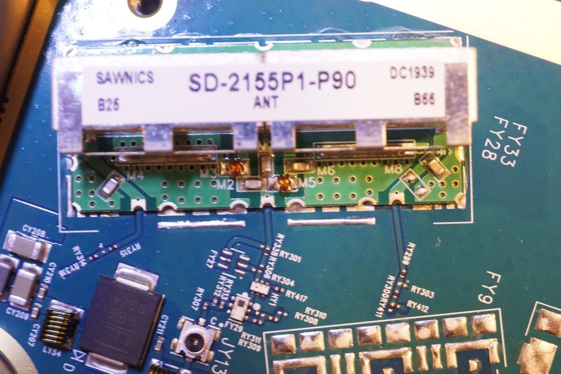
The downlink broadcast antenna side of circuitry looks quite similar. This is somewhat to be expected. Note that the antenna duplexer module is mounted on an angle to minimize any coupling between the downlink and uplink signals.
I am quite impressed with the performance of this signal booster as after installation I am have 4 bar 4G signal through out the house, even in my basement.
A video of this teardown is included below, you can also see the Wave application in action.

