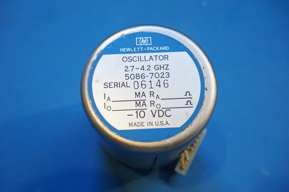
I was going through some of the components I accumulated over the years and stumbled upon a Hewlett Packard YIG tuned oscillator (part number 5086-7023) that I bought a while back. This YIG oscillator was made for a frequency extension module for the HP 8660C synthesized signal generator and has a tunable range of between 2.7 to 4.2 GHz.
YIG oscillators are some fascinating microwave devices. They utilize Yttrium iron garnet’s tunable resonance frequency in the microwave range when immersed in an external magnetic field to achieve a wide tuning range. YIGs also have very high resistivity and very sharp ferromagnetic resonance peaks (namely, high Q factor). These properties make them ideal candidates for tunable oscillators and tunable filters.
I did a teardown of the YIG oscillator used in my Wavetek 907 signal generator a long while back. If you are interested to see the inner workings of a YIG, you can check it out there.
YIGs used in HP test equipment unfortunately do not share the industry standard pintout other YIG manufacturers follow. Joseph Haas at KE0FF has a great write-up on how to hook up this specific YIG.
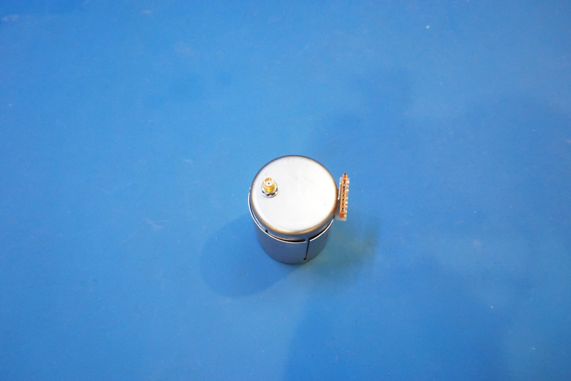
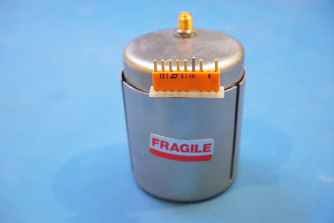
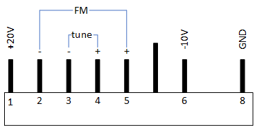
The picture and the diagram below show the pinout of this 8086-7023 YIG oscillator. YIGs used in signal generators typically incorporate heaters for the YIG sphere to achieve maximum temperature stability. This one though, since it is used for sweeping operation, frequency stability is not as important and thus no heater is included.
The YIG oscillator used in the Wavetek 907 utilizes a Gunn diode oscillator. Judging from the positive and negative biasing requirements, it is most likely that this HP YIG oscillator uses a bipolar junction transistor in its oscillator circuitry.
Powering up a YIG oscillator is rather straightforward. Besides the +20V and -10V DC biasing, the only other required connections are pin 3 and pin 4 which is the main tuning coil. The FM coil is used for fine frequency adjustments and do not need to be connected if the sole purpose is just to produce an output.
In the experiment setup illustrated below, the biasing voltages are supplied from a dual-rail programming power supply. The current to the main tuning coil is supplied via an HP 6181C current source which is not in the view of this picture. The output current from the HP 6181C is monitored by the BK 2709B multimeter. The current through the FM coil is set via the Array 3711A electronic load due to my lack of another precision current source. Finally the output from the YIG goes to the HP 8566B spectrum analyzer via two 3dB pads for limiting the input power.
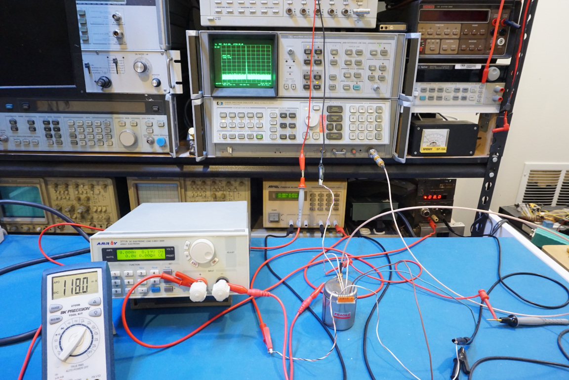
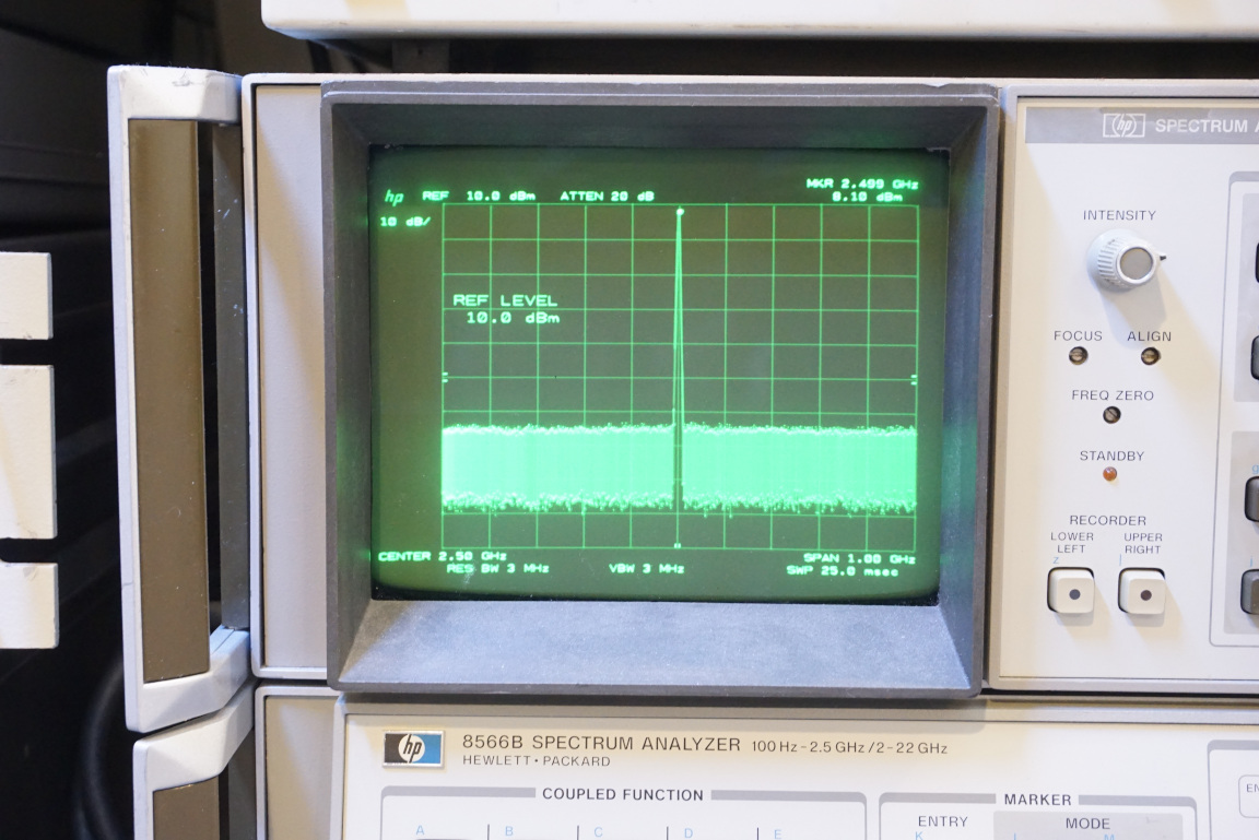
When the tuning current is set at around 118mA, the output frequency from the YIG oscillator is at roughly 2.5 GHz as can be seen in the picture below.
Although the rated tuning range for this YIG is between 2.7 GHz and 4.2 GHz. I was able to adjust the frequency over a much wider range. The frequency of this particular YIG can be tuned down to around 1.437 GHz with a coil current of 66.1 mA, and can be tuned all the way up to 4.505 GHz with a coil current of 216.5 mA. This gives the main coil tuning sensitivity at around 20MHz/mA. The FM coil is roughly 100 times more sensitive at 0.2MHz/mA and thus is suitable for fine tuning the YIG output or for external modulations.
Below is a video further explaining the operating principle of an YIG tuned oscillator and demonstrating the tuning characteristics.

