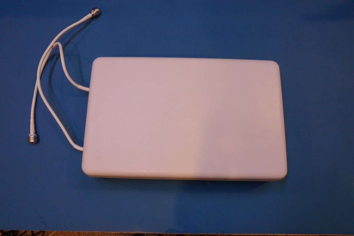
In this blog post, let’s take a look at a cross-polarized dual band MIMO Panel antenna that is designed for cellular signal booster. It can also be used with hotspots and routers within the designated frequency bands.
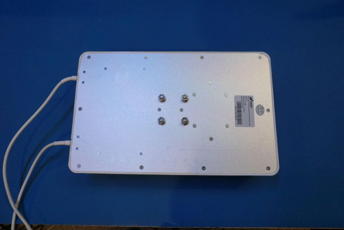
This dual band antenna is designed and made by RSRF. According to the datasheet, it operates between the frequency ranges of 600 to 960MHz and 1690 to 2700MHz with a modest gain of 6dBi and 9dBi respectively. These frequency bands pretty much covers all the cellular frequencies used for 3G and 4G LTE in North America. You can also use this antenna for low-band and mid-band 5G applications. As the low-band 5G lies between 600-850MHz and the mid-band 5G is between 2.5-3.7 GHz. Although this antenna only covers a small portion of the mid-band 5G frequency range.
MIMO antennas essentially contain multiple sets of antennas for increased the signal diversity. In wireless communications, signal diversity is very important. As the radio receiver (e.g. cell phone) moves through a complex environment such as that in an urban setting, the received signal is essentially the summation of all the reflected signals that have taken different paths and depending on the phase of these signals arriving at the receiver from different paths, the combined signal could be stronger or weaker based on these multi-path signals relative phases.
This phenomenon is called multi-path fading. Thus it is advantages to utilize some kind of diversities in the communication system to combat this multi-path fading. In a MIMO antenna system, if antennas are positioned apart with multiple wavelength spacing, spatial diversity can be achieved. In a compact MIMO antenna system like this one however, it is impractical to physically space the different antenna sets out and therefore a pair of orthogonally polarized antennas are often used. This technique is also often referred to as cross polarization.
Signal diversity also increases the throughput of the communication channel, which typically translates into faster download and upload speed. It also increases the signal-to-noise (SNR) ratio with the added diversity gain. All these improves the overall channel capacity according to Shannon-Harley theorem:
\[C=Blog_2\left(1+\frac{S}{N}\right)\]Upon removing the antenna dome, it became apparent that this dual-band panel antenna is consisted of two sets cross-polarized dipole antennas. The smaller antenna is used for the 1690 to 2700MHz frequency band and the larger set to the right is used for the 600 to 960MHz frequency band.
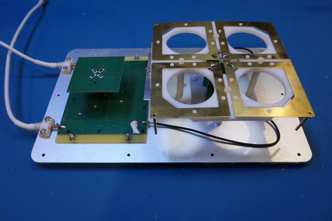
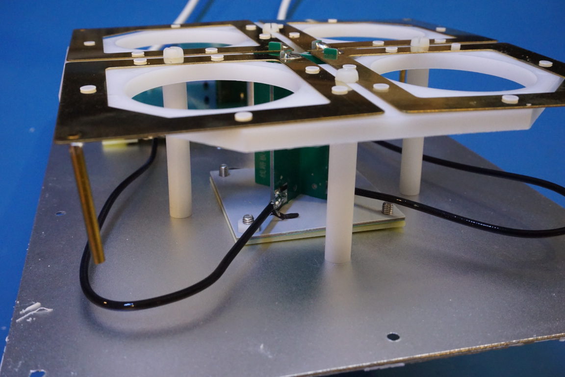
The dipole designs for both the high frequency band and the low frequency band are similar although are built using different techniques. The larger antennas are made with gold-plated copper and are supported by some low RF loss material (could be either ABS or PTFE). In the picture to the right below, you can see some rod structures hanging off the corners of each arm of the dipole. I believe these are inductive elements and are used to fine-tune the frequency response of the antenna. The wide aperture of the looped design increases the dipole operating bandwidth.
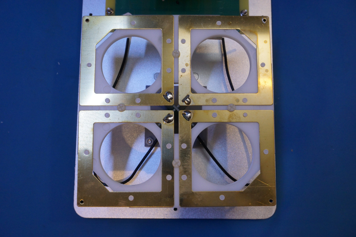
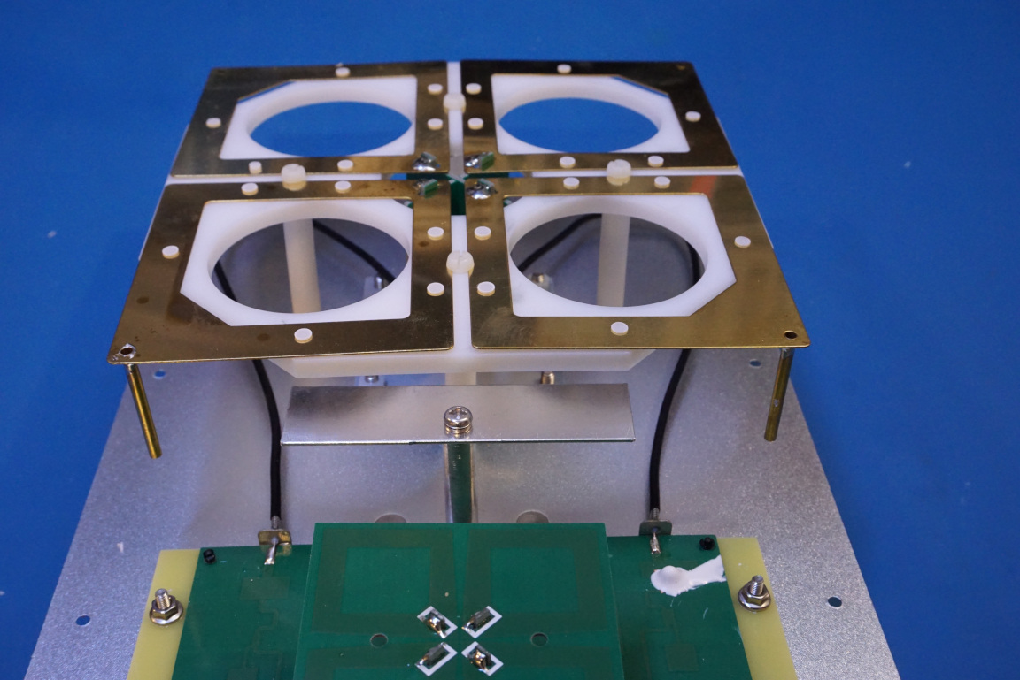
In this picture below, you can see the feed lines feeding into the two orthogonally arranged dipole pairs.
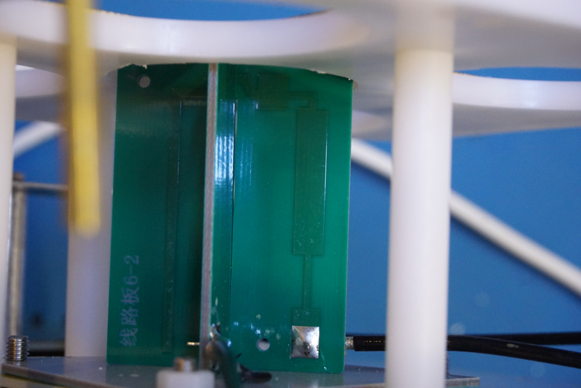
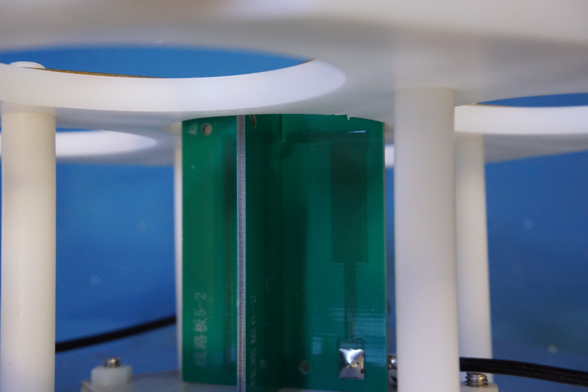
Here are a couple of pictures of the smaller antenna that is used for the 2GHz frequency band. Because of the smaller size, the antenna features are etched onto the PCB instead of using separate materials like we saw for the low frequency band antenna.
In the GHz range, choosing the right PCB material becomes critical as the non-linearity in the PCB dielectric substrate causes passive intermodulation and generates unwanted harmonics. The PCB material used for high frequency antennas also has low RF loss. Likely the material used here is PTFE rather than the standard FR4.
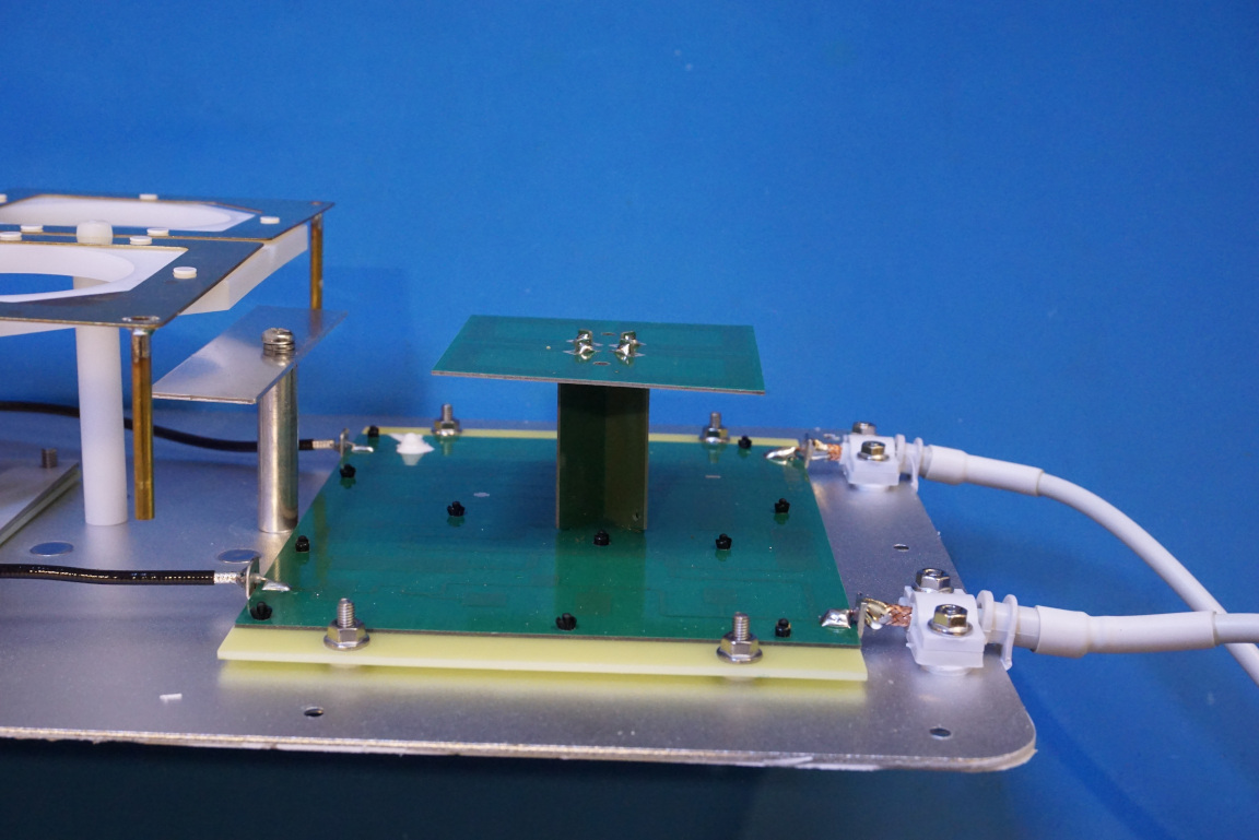
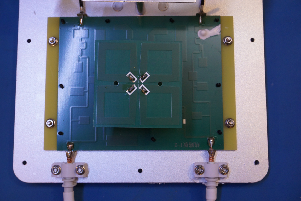
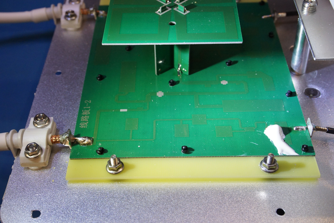
Since for each of the polarization there are two separate antennas (one for lower frequencies and one for higher frequencies) fed from a single coax, a diplexer is needed to multiplex the these two frequency contents. In the picture below, you can see the distributed-element filter design for the diplexer implemented on the PCB. You can also clearly see that the input signal from the input coax splits into two distinct paths: upon filtering, one path goes to the smaller antenna via PCB trace and the other one goes to the larger antenna via a coax.
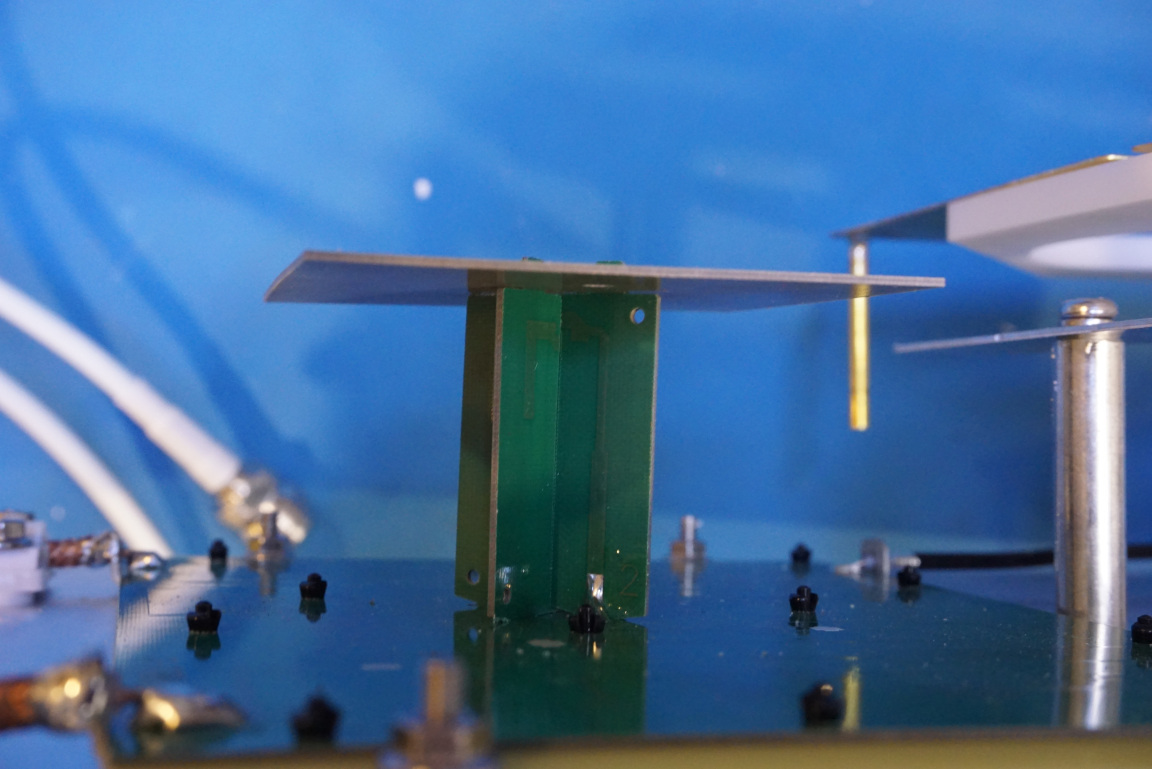
In these pictures, you can see the baluns implemented on the vertical PCB supports. These are essentially RF transformers that convert the single ended input from the coax into the balanced differential signal that drives the dipole antennas.
Here is a video of this teardown:

