I bought a couple of IXYS linear MOSFETs (IXTK90N25L2) a while ago to test their capabilities when used as electronic load, and the result was quite impressive. So I decided to build another electronic load using both MOSFETs. As you can see in the video towards the end, this electronic load can sink more than 100 Amps of current while dissipating more than 400W continuously and can withstand more than 1kW of power dissipation in pulsed operation mode.
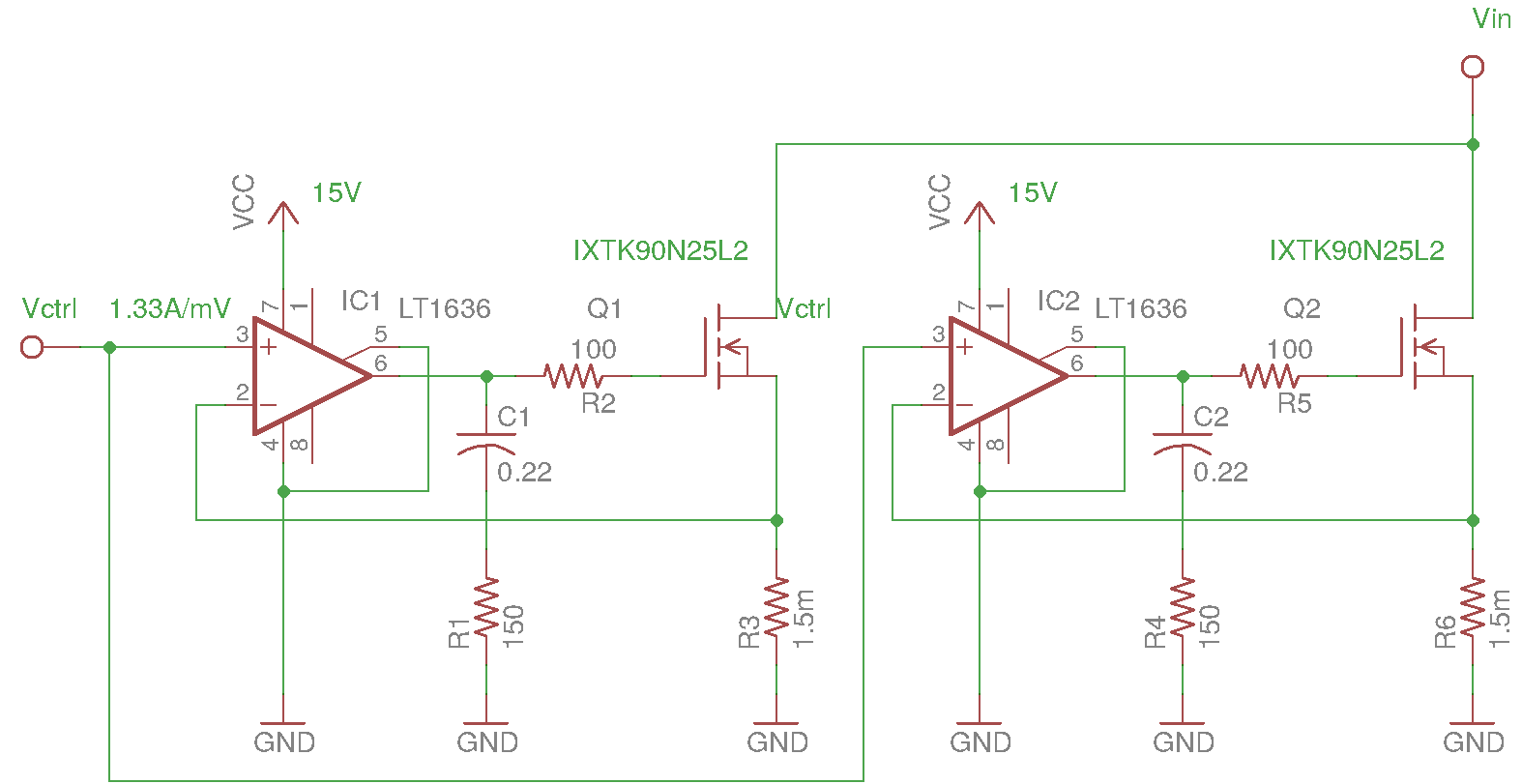
The circuit is almost identical to the one I used in my previous experiments. Instead of using a single MOSFET, two MOSFETs are used. Each channel is identical. When the voltage control inputs and the drains of the MOSFETs are tied together, the load is essentially divided equally between the two MOSFETs. I used two 50A/75mV current shunt resistors as the feedback resistors. The obvious benefit in choosing such small resistance value (each shunt is only 1.5mΩ) is that the voltage drop is virtually negligible. Even when handling an 100A load, the voltage drop across each shunt resistor is only going to be 75mV.
The downside of using such low valued shunt resistors is that it requires the opamps to have extremely low input offsets as even a small offset can introduce a large error in controlled drain-to-source current. For instance for my particular setup, a 100µV offset voltage would cause a 133mA change in the load current. Also, it is difficult to generate such low and stable control voltages without using precision DACs and precision opamps. My intention was to use this electronic load with my Krohn-Hite MV216A voltage standard so generating a low and stable control voltage is not an issue (MV216A has a voltage resolution of 0.1µV in the mV range). If you plan to use a microcontroller to control the load like I did in my previous electronic load build, you will need to either use precision opamps to amplify the shunt voltages to a range that is compatible to your DAC’s output (e.g. 0-5V) or use a low tempco precision voltage divider to generate the mV range control signal.
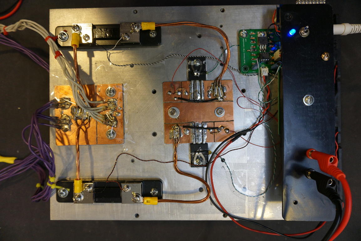
The entire circuit was built on protoboards and placed on top of a large aluminum block. The surface of the aluminum block was polished slightly to ensure good thermal conduction between the TO-264 package and the heatsink. 2oz copper clad was used for higher current carrying capabilities in the high current portion of the circuit. All the wiring on the main current path are done using at least 6 AWG equivalent wires to ensure that they can handle at least 100A without significant heat-up or voltage drop.
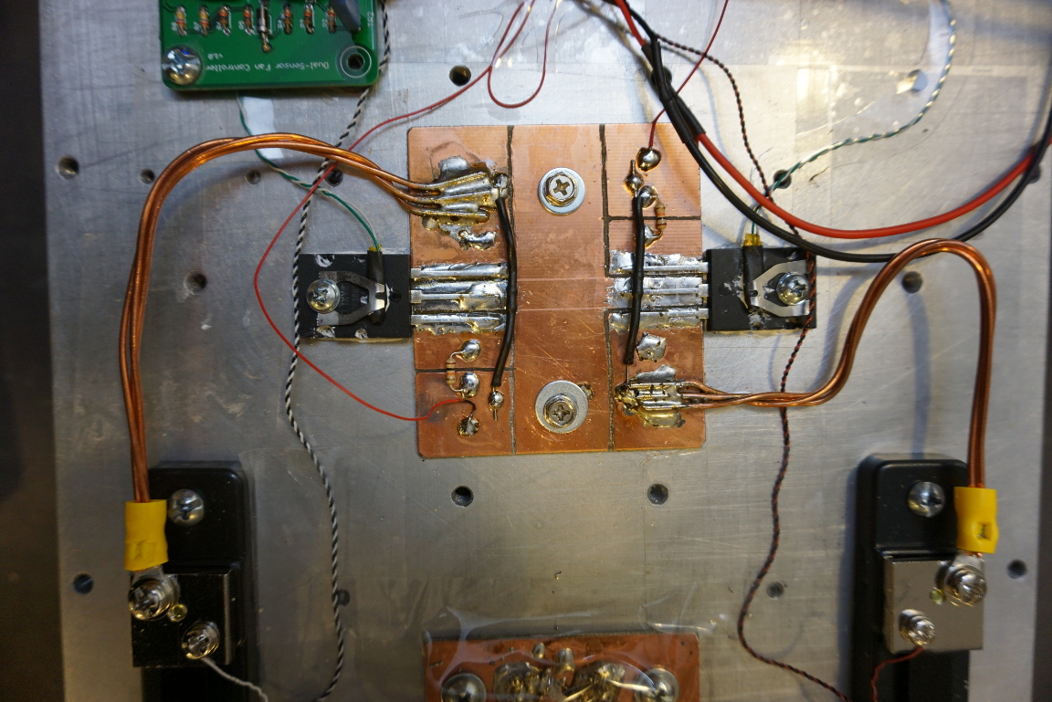
Here is a closeup picture of the two MOSFETs. A thermistor which controls the cooling fans is clamped onto each MOSFET’s surface. If you are interested in the dual-sensor fan controller, you can take a look at my post here.
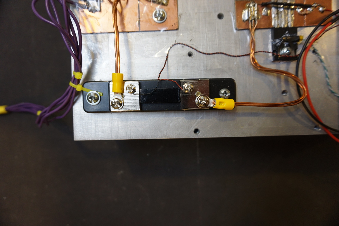
Notice that the current shut is wired using 4-wire Kelvin sensing, this is important as the shut resistance is only 1.5mΩ.
The following is a picture showing the board that houses the two LT1636 rail-to-rail OpAmps. A DC-DC converter is used to convert the input voltage (15V to 20V) down to 12V for the fan controller circuit and the cooling fans.
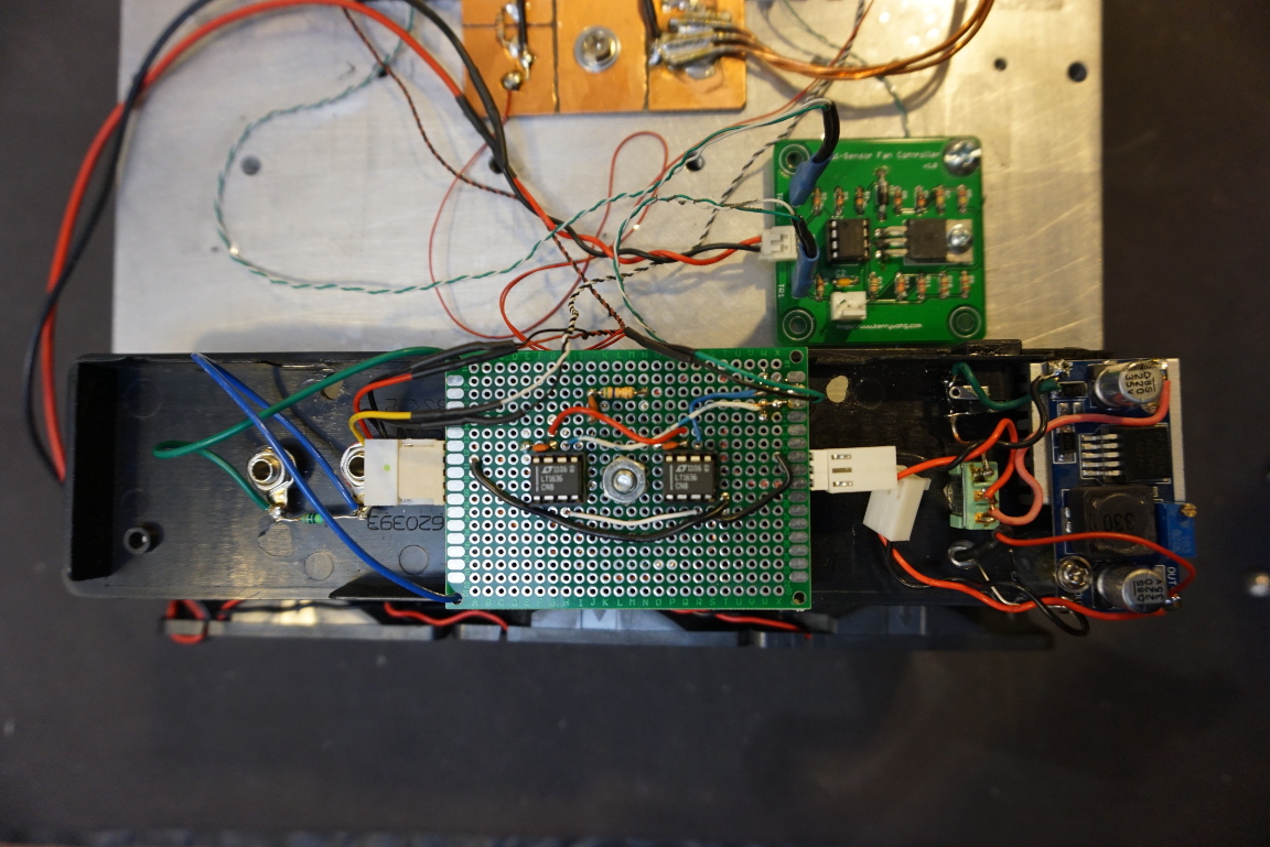
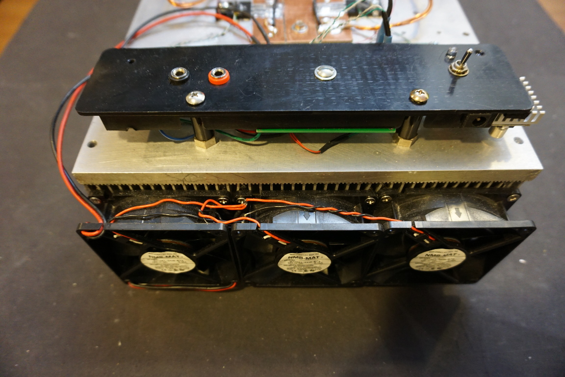
And here is a picture showing the controller board mounted. You can also see three cooling fans on the side of the heatsink.
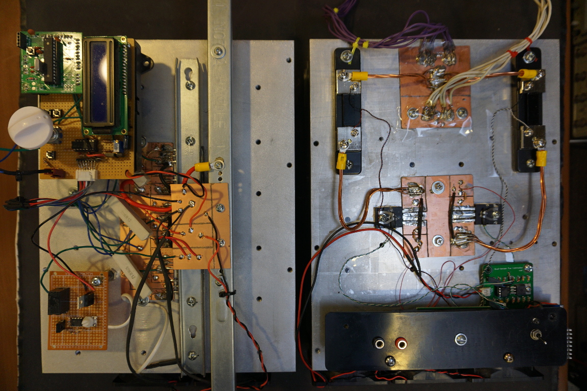
I built an Arduino controlled electronic load back in 2013. That electronic load used six IRF150’s but was only able to dissipate around 150W before one of the MOSFETs suffers secondary breakdown. Here is a picture of both of these electronic loads side by side. Yes, they were built with the same kind of heatsinks. I bought two of those in an auction and now they are both put to good use.
In the video below, you will see me testing a 3.3V 80A and a 12V 85A power supply.

